Chapter 3. Operation
22
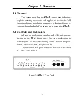
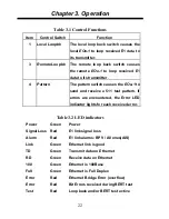
Table 3.1 Control Functions
Item Control
Switch
Function
1
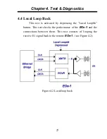
Local Loopbk
The local loop back switch causes the
local EOe-1 to loop received E1 data to
its transmitter.
3
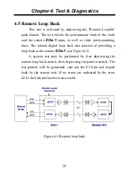
Remote Loopbk
The remote loop back switch causes
the remote EOe-1 to loop received E1
data to its transmitter.
4
Pattern
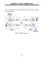
The pattern switch causes the EOe-1 to
send and receive a 511 test pattern. If
errors are encountered, the Error LED
indicator lights for each received error.
Table 3.2 LED indicators
Power Green
Power
Signal Loss Red
E1 link signal loss
Alarm
Red
E1 link alarms: BPV / All ones(AIS)
Link
Green
Ethernet link is good
TD
Green
Transmit data on Ethernet
RD
Green
Receive data on Ethernet
100
Green
Ethernet is 100Base
Full
Green
Ethernet is Full Duplex
Error
Red
Ethernet Bridge Error (overflow)
Error
Red
Bit Errors received during BERT test
Test
Red
Loop back and/or BERT test active
Summary of Contents for EOe-1
Page 1: ...USER MANUAL EOe 1 10 100Base Ethernet over G 703 Unframed E1 ...
Page 2: ......
Page 4: ......
Page 18: ...Chapter 1 Introduction 12 This page left blank intentionally ...
Page 26: ...Chapter 2 Installation 20 This page left blank intentionally ...
Page 43: ......

