


MINI TRACKED DUMPER
25
GB
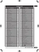
PARTS LIST
No.
Description
Q'ty
1
Plate
1
2
Washer ø6
20
3
Spring washer 6
12
4
Nut M6
9
5
Handle sleeve
2
6
Throttle Cable
1
7
Throttle Lever
1
8
Hoop
1
9
Screw M6x60
1
10
ON/OFF Switch
1
11
Right/Left Steering Lever
2
12
Screw M6X35
1
13
Right/Left Steering Lever Cable
2
14
Right Handle Frame Assembly
1
15
Bolt M6x45
5
16
Screw M6x16
1
17
Left Handle Frame Assembly
1
18
Clutch Control Lever
1
19
Clutch Control Lever Cable
1
20
Screw M5x20
2
21
Nut M5
2
22
Baseplate (L)
1
23
Bolt M8x16
12
24
Washer ø8
58
25
Screw M10x20
8
26
Washer ø10
28
27
Washer ø10
28
28
Handle Mounting Frame
1
29
Nut M8
25
30
Bolt M8x25
8
31
Bolt M8x20
5
32
Washer ø8
13
33
Baseplate (R)
1
34
Small Pulley Cover
1
35
Engine(6.5HP)
1
36
Key 5x35
1
37
Fixing bracket
1
38
Tensioner Pulley Bracket
1
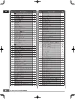
No.
Description
Q'ty
39
Washer ø8
2
40
Belt Plate
1
41
Sleeve Washer
1
42
Small Pulley
1
43
Belt B33
1
44
Brake Cable
1
45
Screw M10x70
1
46
Hand Grip
1
47
Driving Wheel
2
48
Lock Nut M10
15
49
Screw M10x60
2
50
Gearbox Complete
1
51
Big Pulley Guard
1
52
Bolt M6x20
1
53
Screw M5x12
1
54
Circlip 35
1
55
Circlip 15
1
56
Bearing 6202-2RS
2
57
Tensioner Pulley
1
58
Wheel Shaft Press Plate
2
59
Belt Plate
1
60
Connecting Angle Block
1
61
Bolt M6X25
2
62
Support Plate( R )
1
63
Bolt M8X50
2
64
Washer
2
65
Bolt M8X45
2
66
Cable Fixing Bracket
1
67
Rubber Cushion
4
68
Bolt M10x65
8
69
Nut M8
4
70
Support Plate (L)
1
71
Long Extension Sping
1
72
Gasket 25x47x7
8
73
Bearing 6204-2RS
16
74
Supporting Wheel weldment
8
75
Washer
10
10
76
Bolt M10X25
12