


MINI TRACKED DUMPER
2
GB
TABLE OF CONTENTS
ENVIRONMENTAL
Specifications
INTRODUCTION
Introduction
2
Specifications
2
Symbols
3
Safety
4
General Safety Rules
4
Specific Safety Rules
6
Unpacking The Container
7
Contents Supplied
8
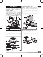
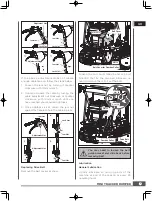
Assembly
9
Know your Machine
12
Features & Controls
12
Operation
14
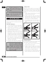
Maintenance
16
Storage
20
Trouble Shooting
21
Parts Schedule
22
Parts Lists
25
Y
our n
ew
min
i
trac
ked
du
mp
er will more
than satisfy your
expec
tat
i
ons
.
It has
bee
n
m a n u f a c t u r
e d
u n d e r s t r i n g
e
n t q u a l
i
t y
standards to meet superior performan
c
e
criteria. You
wi
ll find
i
t easy and saf
e
to
operate, and with proper care, it will give you
many years of dependable service.
Carefully read through this entire
operator’s manual before using this
unit. Take special care to heed the
cautions and warnings.
Re
c
ycl
e
unwant
ed
mat
e
rials instead
of
d
is
p
osing of t
hem
as
w
aste.
A
ll
tools,
h
oses and pa
ck
ag
i
ng should
be
resort
e
d, tak
e
n to t
he
lo
c
al
re
c
ycling
ce
nter and
di
spose
d
of
i
n
an environment-friendly safe way.
The
four-s
peed
g
e
ar
b
o
x
, thr
ee
forward and
on
e
revers
e
, lies at t
he
he
art of the unit.
I
t
i
s
ov
e
rsized so as to manage saf
e
ly th
e
huge
torques g
e
nerated by the
e
ngin
e.
T
hanks to
i
ts
e
ffi
cie
nt redu
c
t
i
on g
e
ar
i
ng,
i
t
i
s
c
apabl
e
of
moving around in every situation and bearing
any load.
The
Engine manufacturer
is respons
ib
le
for all engin
e
-r
e
lat
ed
i
ssues
wi
th r
e
gards to
pe
rforman
c
e, po
w
er rating, s
peci
ficat
i
ons,
w
arranty and s
e
rv
ice.
Please ref
e
r to the
Engine Manufacturer
’
s o
w
ner’s/operator’s
manual, pa
cked
s
e
parat
e
ly
wi
t
h
your unit, for
more information.
Item No.
QTP500B
Engine
196cc, 6.5HP
Transmission
3F+1R
Load Capacity
500 kg
Box Length
1025-1155 mm
Box Width
600-860 mm
Box Depth
325 mm
Track Width
180 mm
Sound power level
101 dB(A)
k=2 dB(A)
Sound pressure level
81.5 dB(A)
k=2 dB(A)
Vibrating level on
handlebar grips
Left
10.1 m/s
2
k=1.5 m/s
2
Right
11.3 m/s
2
k=1.5 m/s
2
Weight
228 kg