


MINI TRACKED DUMPER
15
GB
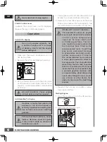
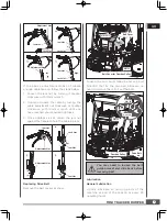
Rapid retraction of the starter cord
(kickback) will pull your handand arm
toward the engine faster than you
can let go. Broken bones, fractures,
bruises, or sprains could result.
SLOW
FAST
OPEN
CLOSED
Operating
After the engine warms up, move the throttle
lever to accelerate engine speed.
Engage the required gear and slowly squeeze
the clutch control lever. If the gear does not
engage immediately, slowly release the clutch
lever and try again. In this way the power
trackbarrow will start moving.
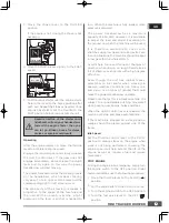
The power trackbarrow has the steering levers
on the handlebars, which makes steering
very easy. To turn right or left, simply pull the
corresponding right or left steering lever.
The sensitivity of the steering increases in
proportion to the speed of the machine and
the load. With an empty machine, a light
pressure on the lever is all that is needed to
turn. When the machine is fully loaded, more
pressure is required.
The power trackbarrow has a maximum
capacity of 660 LBS. However, it is advisable
to assess the load and adjust it according to
the ground on which the machine will be used.
It is therefore advisable to cover such
stretches using low gear and taking extra care.
In such situations, the machine should be kept
in low gear for the whole stretch.
Avoid sharp turns and frequent changes of
direction while driving on rough, hard terrains
full of sharp, uneven points with a high degree
of friction.
Even though the unit has rubber tracks,
remember to be careful when working in
adverse weather conditions (ice, heavy rain
and snow) or on types of ground that could
make the power trackbarrow unstable.
Please note that as this is a tracked vehicle, it is
subject to a considerable pitching movement
when passing over bumps, holes and steps.
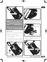
When the clutch control lever is released, the
machine will stop and brake automatically.
If the machine is stopped on a steep slope, a
wedge should be placed against one of the
tracks.
Idle Speed
Set the throttle control lever to the SLOW
position to reduce stress on the engine when
work is not being performed. Lowering the
engine speed will help extend the life of the
engine, as well as conserve fuel and reduce
noise level.
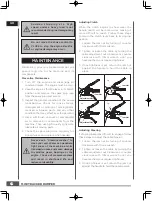
STOP ENGINE
To stop the engine in an emergency, simply turn
the engine switch to the OFF position. Under
normal conditions, use the following procedure:
Move the choke lever to the CLOSED
position.
If the engine is hot, closing the choke is not
necessary.
Move the throttle lever slightly to the FAST
speed.
Pull the recoil starter until the engine starts.
Return the recoil to the home position after
each pull. Repeat the steps as needed. Once
engine has started, set the throttle to the
FAST position before you operate the unit.
Move the throttle lever to the SLOW (
)
position.
Let the engine idle for one or two minutes.
Turn the engine switch to the OFF position.
Turn the fuel valve lever to the OFF (
)
position.
3.
4.
5.
1.
2.
3.
4.
SLOW
FAST
OPEN
CLOSED