background image

Setting the DIP switches of the Interface Box.

DIPs 1 and 2 on the back of the interface-box is used to set the monitor size. DIP 3 must be set to OFF.

After each change of the DIP switch settings you have to execute a power reset of the interface box!

Crux Interfacing Solutions • 21541 Nordhoff Street, Unit C, Chatsworth, CA  91311

phone: (818) 609-9299 • fax: (818) 996-8188 • www.cruxinterfacing.com

rev.072419

2 of 12

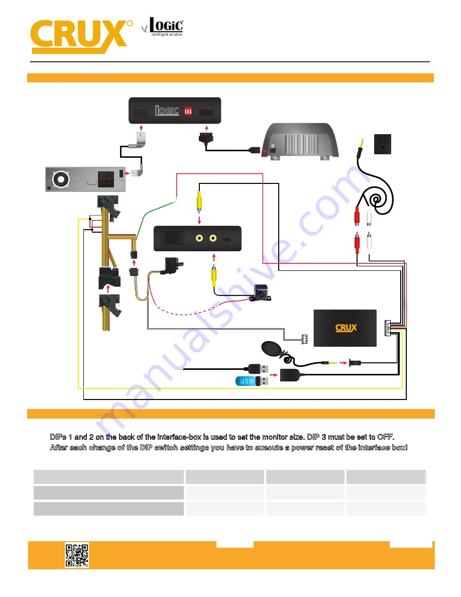
INSTALLATION DIAGRAM:

R

INTERFACING SOLUTIONS

ACPBM-77X

DIP SWITCH SETTINGS:

LVDS OUT

LVDS IN

+12V Switching

Output 1 (Pink Wire)

Rear-View

Camera

(Not Included)


10-pin factory 

LVDS Cable

LVDS10 Cable

Back-Side of Factory

LCD Screen

*If using OEM Back-up

camera, leave REAR CAM

input unoccupied.*

*If installing after-market Back-Up

camera, use the pink wire to provide power to

to the camera, if not, please ignore this connection*

ACPBM-77X

Vehicle Harness

UA
RT

POWER/VIDEO

Smart-Play Module

Vehicle Auxiliary

Input (AUX input) 

Female RCA to

3.5mm jack

Male L & R RCA

Outputs (Audio)

AUX

POWER / CAN

FRONT

CAM

REAR

CAM

FW

UPDATE

Smartphone Cable

USB Input

OR

12V Green Output 2

to ACC power

(on Smart-Play Harness)

Power/CAN

Harness

iDrive Knob

Retention Cable

LVDS

IN

LVDS

OUT

v.

1 2 3

O N

Intelligent Solution

ACPBM-77X Module

ACC Power

Ground

Constant

Back of Headunit


See Warning below 


Setting the DIP Switches of the VRFBM-77D 


DIPs 1 and 2 on the back of the interface box are used to set the monitor type. The default se

ng is: 


Vehicle / N avigation 

Dip 1 

Dip 2 

Dip 3 

M-ASK 

OFF 

No func

�on


No func

�on


CCC 

ON 

No func

�on


No func

�on


WARNING:  


1. DO NOT connect the Quadlock Connector to Factory Radio CD Headunit UNLESS the 10 Pin LVDS Cable has 

been properly and completely connected to factory display and all the other 10 Pin LVDS cable connections have 

been made according to the wiring diagram above or the factory display will be damaged; 


2. DO NOT connect the 10 Pin LVDS Cable when the Radio is Powering ON or the factory display will be damaged; 


3. When the Radio CD Headunit is active (powered ON ), DO NOT disconnect any of the 10 pin LVDS Connections 

or the factory display will be damaged.  


2 / 10 

Rev.040816 

Smart-Play Integration with Rear-View Camera Input for

E Series BMW with CCC Systems (6.5” or 8.8” Monitor) and 10-Pin LVDS Connector

Summary of Contents for ACPBM-77X

Page 1: ... max 1A for the camera power NOTE Android Phones must have a firmware version of 8 and above For 2007 up vehicles without a factory AUX input add on the CRUX AUX BM4 for audio For 2007 below vehicles without a factory AUX input add on the CRUX AUX BM5 for audio PRODUCT FEATURES PARTS INCLUDED ACPBM 77X Module Power CAN Harness ACPBM 77X Vehicle Harness LVDS10 Cable 3 5mm to RCA Adapter Smart Play ...

Page 2: ...ay Module Vehicle Auxiliary Input AUX input Female RCA to 3 5mm jack Male L R RCA Outputs Audio AUX POWER CAN FRONT CAM REAR CAM FW UPDATE Smartphone Cable USB Input OR 12V Green Output 2 to ACC power on Smart Play Harness Power CAN Harness iDrive Knob Retention Cable LVDS IN LVDS OUT v 1 2 3 O N Intelligent Solution ACPBM 77X Module ACC Power Ground Constant Back of Headunit See Warning below Set...

Page 3: ...anel using a trim removal tool 3 Pull out the front panel 4 Remove the 2 torq screws T 10 under the LCD panel s hood 5 Remove the two screws bracing the A C control panel 6 Remove the A C control panel 7 Remove the LCD screen panel 8 Unplug the gray LVDS connector from the back side of the LCD monitor 9 Plug in the LVDS10 cable in place of the factory gray LVDS connector Smart Play Integration wit...

Page 4: ...iliary Input Interface kit CRUX AUX BM4 if your vehicle has factory AUX skip steps 14 16 15 Remove the 12 pin connector wire side view from the factory Quadlock connector Insert the pins from the AUX BM4 harness as follows White Pin 2 Red Pin 7 Black Pin 8 16 Plug in the OBD coder in to the ve hicle s OBD port to the factory system Once the module s LED turns green you can remove the coder 17 Plug...

Page 5: ...ower Video harness to the green 12V output on the ACPBM 77X harness 23 Plug in the female side of the ACPBM 77X harness to the Headunit 24 Plug the Video Out from the Smart Play Power Video harness into the FRONT CAM input on the module 26 If installing an aftermarket back up camera plug the camera s video out to the REAR CAM input on ACPBM 77X module Use the PINK power output 1 wire provided on t...

Page 6: ...ess to the UART port on the Smart Play module 33 Connect the Power Video harness to the POWER VIDEO port on the Smart Play module 36 Check the OSD settings and make sure they match those on the next page Test the Back Up camera Put gear in reverse and check for rear camera image on screen Go to Smart Play mode and test for functionality Once the cameras and Smart Play validation is complete mount ...

Page 7: ...tem OSD POS X 0 xxx POS Y 0 xxx Size Small Small OSD menu window Large Large OSD menu windows Osd TimeOut 2 20 Info Version X XX XX Displays the current SW version Factory Reset CONNECTING THE SMART PLAY INTERFACE plugged in to the USB port using the smartphone s OEM charger data cable The USB port on the ACPBM 77X can be used to charge the Apple device or play videos or music from a USB thumb dri...

Page 8: ...ppears on the screen the BT device name and pairing code 0000 device and connect to CRUX Smart Play_XXXX 4 Once the ACPBM 77X has connected via Bluetooth it 5 Use the iDrive knob to navigate the cursor to the 6 Image above shows the Home Screen once the smartphone is connected Smart Play Integration with Rear View Camera Input for E Series BMW with CCC Systems 6 5 or 8 8 Monitor and 10 Pin LVDS Co...

Page 9: ...Video In Mo on deac vated NOTE The Video In Mo on func on is permanently ac ve without disturbing the naviga on performance Selecting theInterface as Current AV Source Smart Play Integration with Rear View Camera Input for E Series BMW with CCC Systems 6 5 or 8 8 Monitor and 10 Pin LVDS Connector Display settings for Smart Play Adjust brightness contrast and saturation for a more defined image To ...

Page 10: ...ger output deactivated Crux Interfacing Solutions 21541 Nordhoff Street Unit C Chatsworth CA 91311 phone 818 609 9299 fax 818 996 8188 www cruxinterfacing com rev 072419 10 of 12 R INTERFACING SOLUTIONS ACPBM 77X Tip We recommend for all camera to use power out setting Cam and for Smart Play the power out setting of CAN Smart Play Integration with Rear View Camera Input for E Series BMW with CCC S...

Page 11: ...TERFACING SOLUTIONS ACPBM 77X OSD Settings You can change the basic configurations of the interface in the OSD on screen display OSD Menu Menu Item Setting Description OSD POS X 0 xxx Horizontal position of the OSD POS Y 0 xxx Vertical position of the OSD Size Small Small OSD menu window Large Large OSD menu windows Osd TimeOut 2 20 Time setting for automatic OSD shutoff Info Version X XX XX Displ...

Page 12: ...onver ble 2007 2013 X5 Sports Ac vity Vehicle 2008 2011 X6 Sports Ac vity Coupe Plug and Play Installa on Media Controller with controls by factory infotainment iDrive Rear view camera input Front camera input Front camera input can also be used as an Auxiliary Video Input Manual switching to rear view camera only for vehicles with PDC bu on Manual return from rear view and front camera cancella o...

Reviews: