Page 3
CDi DriveCore Series Operation Manual
Front Panel Overview
Front Panel Overview
6
7
8
4
9 10
55
3
1
2
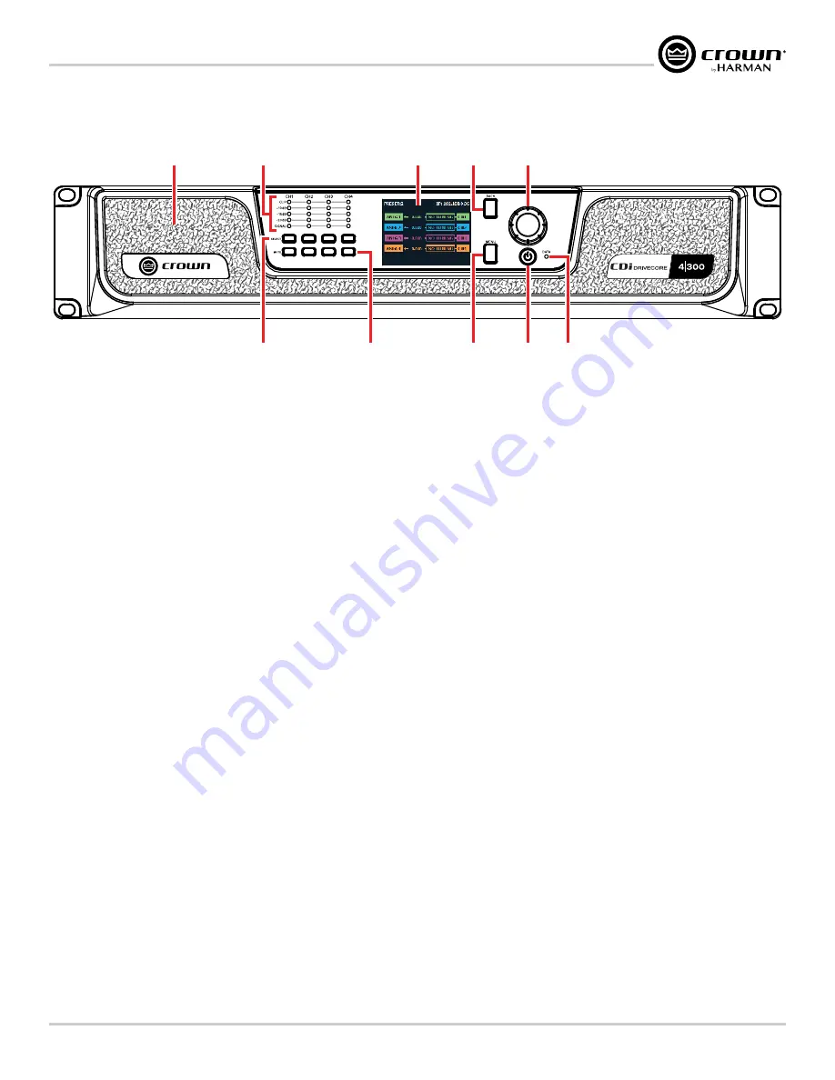
Figure 2:
4|300 front panel shown
1� Cooling Vents/Air Filters
Provides cooling air flow. Do not block or cover these vents.
Air
filters are removable.
2� Signal Level LED Indicators
These LEDs indicate channel signal level as follows:
•
Clip LED –
Lights yellow if the input clips or red if the output
clips. Note that an output clip will always take priority over an
input clip.
•
-10dB LED –
Lights green when the output signal reaches a
level that is 10dB below full scale output of the amp.
•
-15dB LED –
Lights green when the output signal reaches a
level that is 15dB below full scale output of the amp.
•
-20dB LED –
Lights green when the output signal reaches a
level that is 20dB below full scale output of the amp.
•
Signal LED
–
Lights green when signal is sensed at the input.
The threshold for lighting this LED is -40dBu.
NOTE:
The full scale output of the amplifier may change depending
on the Low Z/High Z setting, as well as the amplifier model. See
"Configuring Outputs for Low Z/High Z Operation" on
page 37
for more information.
3� LCD (Display)
This color LCD provides product information and visual feedback for
operating the CDi DriveCore amplifier from the front panel.
4� Back Button
Press this button to navigate back one level when navigating menus.
5� Encoder
This encoder supports rotary and pushbutton operation. It is used to
navigate the CDi DriveCore's menus and select on-screen options. It
is also used to adjust individual channel or overall system volume.
6� Channel Select Buttons
Pressing one of these buttons will select the corresponding channel;
turning the
ENCODER
will then control the volume of the selected
channel.
Pressing and holding a
CHANNEL SELECT
button for 2 seconds
from the Home screen will display a Channel Details screen for
that channel. The Channel Details screen shows additional details
for the selected channel, including configured input source, output
mode, status, channel temperature, and channel volume. Note that
channel volume can also be controlled from this screen by turning
the Encoder.
7� Channel Mute Buttons
Pressing each of these buttons will mute/unmute the corresponding
amplifier output channel. Note that when a channel is muted, the
front panel SIGNAL LEDs will still light to indicate input signal level
presence, the CLIP LEDs will still light to indicate input clipping, and
the LCD will flash "Mute".
8� Menu Button
Pressing this button will enter the Main menu, where amplifier
settings can be edited.
9� Power Button
Turns the amplifier power on or off. The Power button has an
integrated power symbol that illuminates blue when the power is on
and green when the power is off. To prevent the unit from accidentally
being powered off, the Power button must be pressed and held for 2
seconds when powering off.
NOTE:
The Power button is disabled when using the AUX port
"Using the AUX Port" on page 59
for
more information.
10� Data LED
This LED will illuminate yellow when there is valid HiQnet data being
transmitted to/from the amplifier.
NOTE:
4-channel model shown. Indications per channel pair are identical for 2-channel models.
Summary of Contents for 2/300
Page 91: ......


