Page 35
CDi DriveCore Series Operation Manual
Using HiQnet Audio Architect
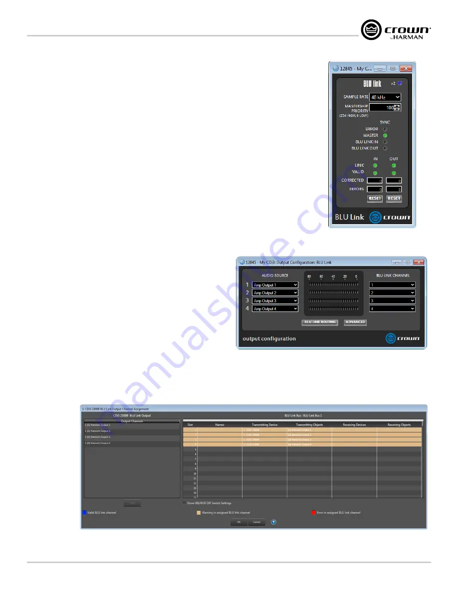
Configuring BLU link Clock
The Advanced Settings panel can be accessed by clicking the
Advanced Settings
button from either
the Input Configuration panel (see
) or from the Output Configuration panel (see
From the Advanced Settings panel, BLU link sample rate and mastership clock priority can be set. This
panel also displays clock sync status and BLU link input/output connection status. Input/output errors
and corrected errors are also displayed and can be reset from this panel. For more information on these
"Configuring BLU link Settings" on page 15
.
Configuring BLU link Outputs
Clicking the
Output Configuration
button from the Input Selector panel (see
link Output Configuration panel (see
). From this panel, audio source signals can be routed
("on-ramped") back onto the BLU link bus as follows:
• Pre-processed audio from the inputs can be routed to the BLU link bus.
NOTE:
The audio from the analog inputs will still pass through the amplifier input gain stage. This
means the signals will be affected by the Gain Mode setting and the input level faders located in the
Input Configuration panel (
) before being sent out to the BLU link bus.
• Amp output channels can be routed to the BLU link bus.
NOTE:
The output audio is bussed from a point at the end of the
amp's signal processing chain and includes the Transducer Thermal
Limiter. This is effectively analogous to taking the audio from the
physical output of the amplifier, which feeds the loudspeaker, and
routing it onto the BLU link bus.
To route amplifier audio onto the BLU link bus, select the audio source for
each output channel using the Audio Source dropdown menus, then select
which BLU link channel to route each signal to using the BLU link Channel
dropdown menus.
NOTE:
Audio Architect also provides the traditional BLU link Output Channel Assignment window (
) for routing BLU link audio onto the BLU
link bus. Either of these methods can be used to assign BLU link output channels.
Figure 38:
Advanced Settings panel
Figure 39:
BLU link Output Configuration panel
Figure 40:
BLU Link Output Channel Assignment window
Summary of Contents for 2/300
Page 91: ......


