Installation
8
English
Example Calculation 2
As example calculation 1 but without the sounder.
Xsafe Bright
pellistor requires a dc supply of 10-30V, at max current in alarm 2
of 95mA. Ensure there is a minimum of 10V at the detector, taking into account
the voltage drop due to cable resistance. For example, a nominal dc supply at the
control panel of 24V has a guaranteed minimum supply of 18V. The maximum
voltage drop is therefore 8V.
Xsafe Bright
can demand up to 95mA and so the
maximum loop resistance allowed is approx 80
Ω
.
A 1.5mm
2
cable will typically allow cable runs up to 3.3km. Table 1 below shows
the maximum cable distances given typical cable parameters for this example
calculation.
C.S.A.
Resistance
(Ohms per km)
Max. Distance
(km)
mm
2
Awg
Cable
Loop
1.0
17
18.1
36.2
2.2
1.5
15
12.1
24.2
3.3
2.5
13
7.4
14.8
5.4
Table 1: maximum cable distances for typical cables
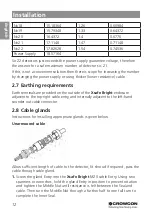
2.6 Cabling Requirement Multidrop MODBUS
This fulfils the requirements of multidrop communications back to a compatible
addressable control panel. Due to current consumption of multiple detectors
powering of accessories via the detector sounder/beacon output or relay contact
must be avoided.
Each detector must be configured with a unique node address when connected
in an addressable network.
Xgard Bright
Xgard Bright
Xgard Bright
Xgard Bright
Control
Panel
Power +V
Power 0V
RS485A
RS485B
Screen
Detectors
Termination
link fitted
here
Beacon/
Sounder


