Crestron Sonnex SWAMP(I)-24X8 Operation Manual Download Page 47

Crestron 

SWAMP(I)-24X8


Sonnex Multiroom Audio System


Operations Guide – DOC. 7049E 

Sonnex Multiroom Audio System: SWAMP(I)-24X8  

  41 

Uploading and Upgrading 

Crestron recommends using the latest programming software and that each device 

contains the latest firmware to take advantage of the most recently released features. 

However, before attempting to upload or upgrade it is necessary to establish 

communication. Once communication has been established, files (for example, 

programs or firmware) can be transferred to the control system (and/or device). 

Finally, program checks can be performed (such as changing the device ID or 

creating an IP table) to ensure proper functioning. 

NOTE:

  Crestron software and any files on the website are for authorized Crestron 

dealers and Crestron Service Providers (CSPs) only. New users must register to 

obtain access to certain areas of the site (including the FTP site). 

Establishing Communication 

Use Crestron Toolbox for communicating with the SWAMP-24X8; refer to the 

Crestron Toolbox help file for details. There are three methods of communication: 

indirect, USB, and TCP/IP. 
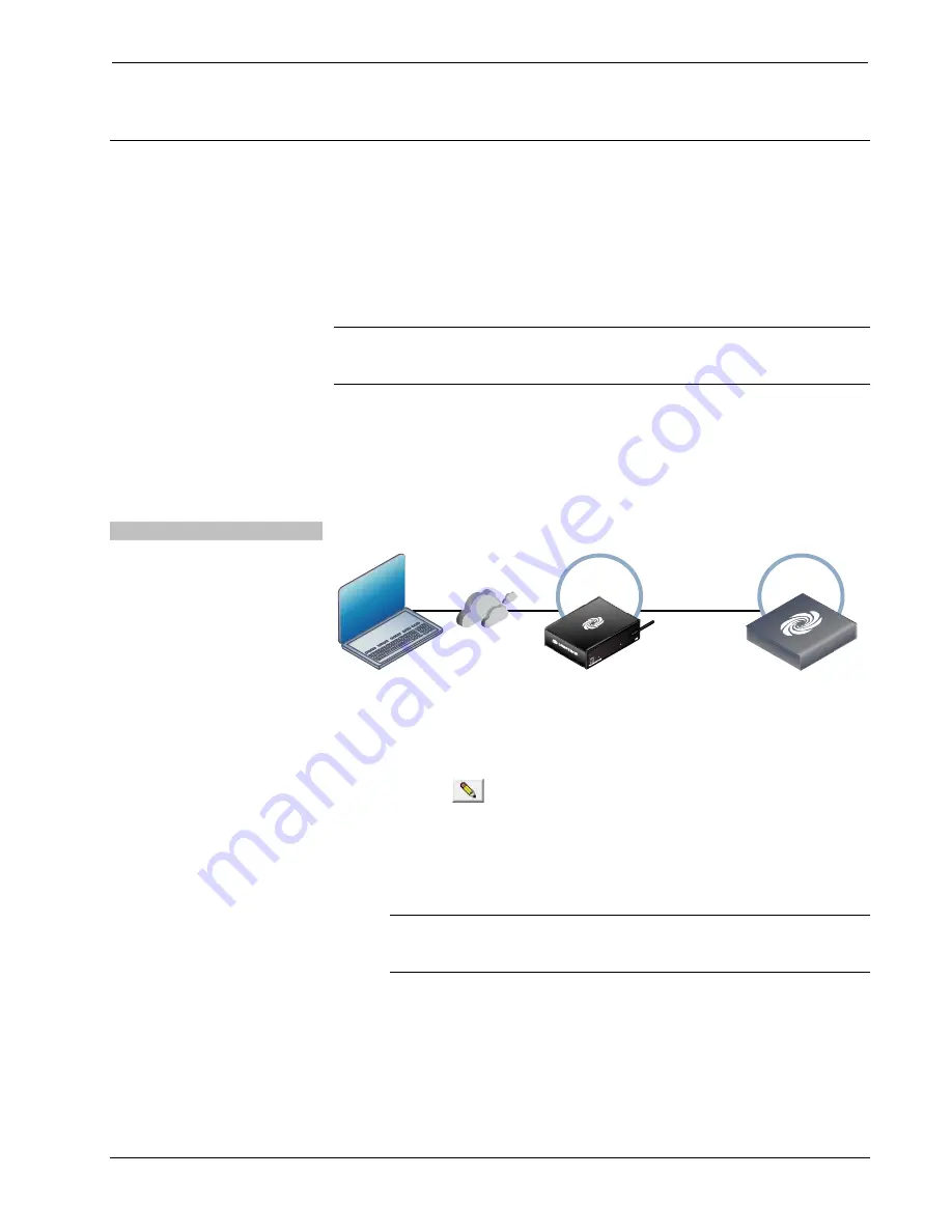
Indirect 

Indirect Communication 

PC Running

Crestron Toolbox

Serial,

or USB

LAN

Cresnet

Control

System

COMPUTER

PWR

NET

HW-R

SW-R

ACQUIRE

ACTIVITY

SWAMP-24X8


SWAMP-24X8 connects to control system via Cresnet: 

1.


Click 

Tools | System Info

2.


Click the 

 icon. 

3.


For 

Connection Type

, select 

Indirect

4.


For 

Device is at

, select 

Cresnet ID

 and select the ID number from the drop-

down menu. 

5.


In the 

Through

 drop-down menu, select the control system. 

NOTE:

  If no address book entry is listed for the control system, click 

Address Book…

 to create an entry. For details, refer to the Crestron 

Toolbox help file. 

6.


Click 

OK

. Communications are confirmed when the device information is 

displayed. 

Summary of Contents for Sonnex SWAMP(I)-24X8

Page 1: ...Crestron SWAMP I 24X8 Sonnex MultiroomAudioSystem Operations Guide ...

Page 2: ...tning flash with arrowhead symbol within an equilateral triangle is intended to alert the user to the presence of uninsulated dangerous voltage within the product s enclosure t hat may be of sufficient magnitude to constitute a risk of electric shock to persons Use only with the cart stand tripod bracket or table specified by the manufacturer or sold with the apparatus When a cart is used use caut...

Page 3: ...n is subject to the following conditions 1 This device may not cause harmful interference and 2 this device must accept any interference received including interference that may cause undesired operation CAUTION Changes or modifications not expressly approved by the manufacturer responsible for compliance could void the user s authority to operate the equipment NOTE This equipment has been tested ...

Page 4: ......

Page 5: ...dware Hookup 20 Configuration 26 Source Setup 26 Zone Setup 27 Expander Status 35 Amplifier Status 36 Network Setup 36 Control Setup 39 About 40 Uploading and Upgrading 41 Establishing Communication 41 Programs and Firmware 42 Program Checks 43 Operation 44 Power 44 Operating Modes 44 Volume Control 45 Problem Solving 46 Troubleshooting 46 Check Network Wiring 46 Reference Documents 47 Further Inq...

Page 6: ......

Page 7: ...ng a unique system topology Sonnex minimizes speaker wiring distances by allowing expansion units to be placed central to the rooms they serve Twenty four stereo channels of uncompressed digital audio and control are routed to each expander over a single inexpensive shielded CAT5e cable Gone is all the clutter of amplifier interconnects and input loop thru cables integrating eight zones of high pe...

Page 8: ...nd loud ambient environments Speaker Profiles allow upload of custom preset speaker settings Sonnex Speaker Protect output limiting affords extra headroom while preventing component damage Individual zone power control and global standby Setup and adjustment via front panel or Sonnex Tools software Remote fault monitoring Seamless Crestron system integration Heavy duty detachable terminal blocks e...

Page 9: ... or TunerRack Modular Multi Tuner CEN TRACK plus digital television receivers and other devices Audio return channels are easily added using Crestron AUD EXT Audio Extenders to receive signals from remote AV receivers located up to 2000 feet 610 m away Sonnex even accepts a direct input from the CEN IDOCV Interface for iPod and other Crestron Home CAT5 Balanced sources without requiring a separate...

Page 10: ...AMP 24X8 s front panel or Sonnex Tools software Advanced DSP To truly deliver an ultimate listening experience in every room Sonnex includes built in digital signal processing providing a virtual arsenal of controls and adjustments intelligently deployed to streamline both the installer setup procedure and day to day user operation Key setup functions are accessible via the front panel while more ...

Page 11: ...tuning the whole system before a single note of music or test signal is even played Output Bussing The spacious open floor plans typical of today s homes and businesses commonly present multiple adjacent listening zones with no sonic boundary between them such as a kitchen and dinette a living room and dining room or an outdoor pool and terrace One click in Sonnex Tools instantly busses adjacent z...

Page 12: ...des several ways to keep tabs on its operating status and health On its own Sonnex possesses the intelligence to protect itself from many types of faults including over temperature over current over voltage under voltage and dc offset on any channel In the event of a fault the front panel LCD provides clear fault indication to speed the troubleshooting of incorrect wiring poor rack ventilation and...

Page 13: ...8 Sonnex Multiroom Audio System Operations Guide DOC 7049E Sonnex Multiroom Audio System SWAMP I 24X8 7 Applications The following diagram shows a SWAMP 24X8 in a multizone application SWAMP 24X8 in a Multizone Application ...

Page 14: ...S PDIF coaxial 2 channel PCM only Output Signal Types Stereo speaker level S PDIF coaxial 2 channel PCM only Sonnex Link Analog to Digital Conversion2 24 bit 48 kHz Source Compensation2 10 0 dB per input Input Monitoring2 Source Signal Detect Digital to Analog Conversion3 24 bit 48 kHz Output Power3 140 watts per channel at 8 ohms 240 watts per channel at 4 ohms 400 watts per channel at 8 ohms bri...

Page 15: ...es 5 band GEQ and SSP settings Bus Volume Offset3 12 0 dB per zone for output bussing Resolution Bitrate4 24 bit 48 kHz Communications Ethernet For control and console 10 100 Mbps auto switching auto negotiating auto discovery full half duplex DHCP Cresnet For control and console Cresnet slave5 Sonnex Link 64 channel 48 utilized digital audio with embedded control auto discovery auto negotiating P...

Page 16: ...L 8G DM 8G CONN WG Cable Connector with Wire Guide for DM CBL 8G DM 8G CRIMP Crimping Tool for DM 8G CONN DM 8G CRIMP WG Crimping Tool for DM 8G CONN WG DM CBL 8G High Performance CAT5e Shielded Twisted Pair Cable ESSENCE Series Essence Speakers EXCITE Series Excite Speakers S EXT1 S Sonnex Link Over Fiber Extender SAROS Series Saros Speakers SAT 70V 100V Sonnex Output Transformer SWAMPE 4 Sonnex ...

Page 17: ...rations Guide DOC 7049E Sonnex Multiroom Audio System SWAMP I 24X8 11 Physical Description This section provides information on the connections controls and indicators available on the SWAMP 24X8 SWAMP 24X8 Physical View Front SWAMP 24X8 Physical View Rear ...

Page 18: ...nnex Multiroom Audio System Crestron SWAMP I 24X8 12 Sonnex Multiroom Audio System SWAMP I 24X8 Operations Guide DOC 7049E SWAMP 24X8 Overall Dimensions Top 18 47 in 470 mm 17 29 in 439 mm 19 00 in 483 mm ...

Page 19: ...16 21 Connectors Controls and Indicators CONNECTORS 1 CONTROLS AND INDICATORS DESCRIPTION 1 LCD Display and BUTTONS Green LCD alphanumeric adjustable backlight 2 lines x 20 characters per line Displays source and zone setup amplifier and expander status network and control configuration volume levels and other parameters 4 Push buttons for execution of LCD driven functions 2 MENU 1 Push button ste...

Page 20: ...ent 7 COMPUTER Pin 3 Pin 4 Pin 2 Pin 1 USB Type B female USB computer console port 6 ft cable included PIN DESCRIPTION 1 5 Vdc 2 Data 3 Data 4 Ground 8 VOLUME 1 Continuous turn rotary encoder adjusts menu parameters defaults to audio volume 9 ZONE 1 10 Buttons and LEDs 10 Push buttons and green LEDs select output zone for routing and adjustment 10 ANALOG SOURCES L R 1 16 32 RCA female comprising 1...

Page 21: ...D indicates data communication on the corresponding output Connect to Sonnex Multiroom Audio Expanders4 5 sold separately 15 S PDIF SOURCES 17 24 8 RCA female S PDIF coaxial digital audio inputs Input Impedance 75 ohms 16 S PDIF OUT 9 10 2 RCA female S PDIF coaxial digital audio outputs Output Impedance 75 ohms 17 LAN Green LED Yellow LED Pin 8 Pin 1 1 8 wire RJ 45 female 10BASE T 100BASE TX Ether...

Page 22: ... 6 L R 7 and 8 L R Red LED indicates bridged operation NOTE Outputs can only be bridged into an 8 ohm load 1 Interface connectors for NET ANALOG SOURCES BALANCED and SPEAKER OUTPUTS ports are provided with the unit 2 Refer to Fuse Replacement on page 25 for additional details 3 Port on SWAMPI 24X8 is labeled 220 240V 50 60Hz MAX 6A 4 For connection of the Sonnex Link between the SWAMP 24X8 and eac...

Page 23: ...computer digital media server and other IP based devices For general information on connecting Ethernet devices in a Crestron system refer to the Crestron e Control Reference Guide Doc 6052 at www crestron com manuals Sonnex Link Wiring Crestron recommends using Crestron DM CBL 8G or high quality CAT5e shielded twisted pair cable for connections between the SWAMP 24X8 and expanders NOTE Shielded c...

Page 24: ...avoided on all sides of the unit Rack Mounting The SWAMP 24X8 can be mounted in a rack or stacked with other equipment Two ears are provided with the SWAMP 24X8 so that the unit can be rack mounted These ears must be installed prior to mounting Complete the following procedure to attach the ears to the unit The only tool required is a 1 or 2 Phillips screwdriver WARNING To prevent bodily injury wh...

Page 25: ... can be removed to provide more space in the rack To install the ears use the following procedure CAUTION To prevent equipment damage use only the rack ears Crestron provides for this device 1 There are screws that secure each side of the SWAMPE 8 top cover Using a 1 or 2 Phillips screwdriver remove the three screws closest to the front panel from one side of the unit Refer to the diagram followin...

Page 26: ...T 100BASE TX Ethernet to LAN NET To Cresnet Devices Ground CAUTION Keep the device unplugged until all of the input network and speaker wiring is complete CAUTION Check the speaker wires for shorts and frayed wiring around the SPEAKER OUTPUTS connectors NOTE Ensure the unit is properly grounded by connecting the chassis ground lug to an earth ground building steel NOTE To prevent overheating do no...

Page 27: ...nput PIN WIRE COLORS 568B AUDIO I O BALANCED INPUT CONNECTION 1 WHITE ORANGE Audio Left Out L 2 ORANGE Audio Left Out L 3 WHITE GREEN Audio Right Out R 4 BLUE N A 5 WHITE BLUE N A 6 GREEN Audio Right Out R 7 WHITE BROWN N A 8 BROWN N A Speaker Connections Make speaker connections to the SWAMP 24X8 as shown in the following diagram Speaker Connections R L NOTE If the SAT 70V 100V Sonnex Output Tran...

Page 28: ... the SWAMP 24X8 must be configured with the Installer Mode menu or with the Sonnex Tools application Refer to Bridge Outputs on page 33 or the Sonnex Tools help file for more information WARNING This amplifier is capable of delivering immense amounts of undistorted power to the loudspeakers Please use caution and adequate ear protection if listening to content at high volume levels as continued ex...

Page 29: ... a Create a low pass filter on the subwoofer zone i Set the filter frequency to the desired crossover frequency ii Set the filter bandwidth to 1 9 b Create a high pass filter on the left right stereo pair zone i Set the filter frequency to the desired crossover frequency ii Set the filter bandwidth to 1 9 Use a 4th order crossover filter a Create two low pass filters on the subwoofer zone i Set bo...

Page 30: ...the SPL meter at the listening position with the meter pointing straight up c Play satellite pink noise wav on the left speaker d Turn the volume up until the SPL meter reads 85 dB e Play satellite pink noise wav on the right speaker The SPL meter should read very close to 85 dB f Play subwoofer pink noise wav on the left speaker g Use Sonnex Tools or the Installer Mode menu to adjust the bus volu...

Page 31: ...until the fuse holder pops out 4 Remove the fuse from the fuse holder and insert a new fuse CAUTION Use only the specified type of fuse Failure to do so may cause damage to the SWAMP 24X8 NOTE Two spare fuses are included SWAMP 24X8 MODEL REQUIRED FUSE TYPE SWAMP 24X8 US and Canada T15AH 1 4 x 1 1 4 250 V 15 A time lag high rupture rated SWAMPI 24X8 International 220 240 VAC T8AH 5 mm x 20 mm 250 ...

Page 32: ...tup configures each output zone s settings for audio Sonnex links busses bridging with other outputs and power output Expander Status provides the status of each connected SWAMPE Sonnex Multiroom Audio Expander Amplifier Status shows the settings and operating status of each of the SWAMP 24X8 amplifiers as well as the amplifiers of connected SWAMPE Sonnex Multiroom Audio Expanders Network Setup co...

Page 33: ...he desired preference Mono sets the zone for mono or stereo sound Minimum Volume specifies the lowest volume to which the zone can be set Maximum Volume specifies the highest volume to which the zone can be set Startup Volume specifies the volume level that is used when a zone is turned on Bussing assigns the selected zone to a group of zones bus Zones in a bus track each others volume and source ...

Page 34: ...de Menu on page 26 2 Enter the Installer Mode menu as described in Enter the Installer Mode Menu on page 26 3 Press q or to display Zone Setup and press ENTER 4 To exit the Zone Setup menu and return to the Installer Mode menu press MENU Set EQ Equalization To adjust a zone s EQ setting perform the following procedure 1 Enter the Zone Setup menu as described in Enter Exit the Zone Setup Menu above...

Page 35: ...ble 0 0 dB q 4 Press q or to display the treble setting to be applied and press ENTER 5 Repeat for every zone to be adjusted 6 Press MENU to return to the Zone Setup menu Set Loudness To adjust a zone s loudness setting perform the following procedure 1 Enter the Zone Setup menu as described in Enter Exit the Zone Setup Menu on page 28 2 Press q or to display Loudness and press ENTER A list of zon...

Page 36: ...n page 28 2 Press q or to display Mono and press ENTER A list of zones is displayed 3 Press q or to display the zone to be controlled and press ENTER The Mono Stereo screen is displayed Mono Stereo Screen Zone 1 Stereo 4 Press q or to display the mono stereo setting to be applied and press ENTER 5 Repeat for every zone to be adjusted 6 Press MENU to return to the Zone Setup menu Set Minimum Volume...

Page 37: ...eturn to the Zone Setup menu Set Startup Volume To adjust a zone s startup volume setting perform the following procedure 1 Enter the Zone Setup menu as described in Enter Exit the Zone Setup Menu on page 28 2 Press q or to display Startup Volume and press ENTER A list of zones is displayed 3 Press q or to display the zone to be controlled and press ENTER The Startup Vol screen is displayed Startu...

Page 38: ...ed and press ENTER The Offset Screen is displayed Offset Screen Zone 1 Offset 0 0 dB q 4 Press the q or buttons to display the bus volume offset setting to be applied and press ENTER 5 Repeat for every zone to be adjusted 6 Press MENU to return to the Zone Setup menu View Bussing Lists To view the zones assigned to a bus perform the following procedure 1 Enter the Zone Setup menu as described in E...

Page 39: ...ng and press ENTER NOTE Bridged outputs are indicated with LEDs near the speaker terminals on the rear of the SWAMP 24X8 and SWAMPE Multiroom Audio Expander 5 Repeat for every zone to be bridged unbridged 6 Press MENU to return to the Zone Setup menu Set Speaker Wattage Rating To specify the wattage of speakers connected to a zone output perform the following procedure 1 Enter the Zone Setup menu ...

Page 40: ...dure NOTE As speaker ratings vary greatly across manufacturers there is no guarantee that Sonnex Speaker Protect protects against speaker damage in all situations 1 Enter the Zone Setup menu as described in Enter Exit the Zone Setup Menu on page 28 2 Press q or to display Speaker Protect and press ENTER A list of zones is displayed 3 Press q or to display the zone to be configured and press ENTER ...

Page 41: ...TER A list of Global EQ settings is displayed 3 Press q or to display the desired setting and press ENTER Confirm Global EQ Setting Screen Are You Sure Yes 4 Press q or to display Yes or No and press ENTER The display returns to the Zone Setup menu Expander Status Select this option to view the status and information about devices that are connected to the SWAMP 24X8 To view information perform th...

Page 42: ...on for a specific zone perform the following procedure 1 Press q or to display the desired zone and press ENTER 2 Press q or to scroll through the available information 3 Press MENU to return to the Amplifier Status menu 4 Press MENU to return to the Installer Mode menu Network Setup Select this option to configure and view the SWAMP 24X8 network settings Enter Exit the Network Setup Menu To enter...

Page 43: ...ed Subnet Mask Screen Subnet Mask 255 255 255 000 3 Press q or to set the first octet of the subnet mask 4 Press the button under the next octet or press ENTER to move to the next octet to select it for editing 5 Repeat steps 3 and 4 for each octet 6 To save the subnet mask and return to the Network Setup menu move the cursor to the right most octet and press ENTER To cancel the operation and retu...

Page 44: ...r communication To enable or disable WINS perform the following procedure 1 Enter the Network Setup menu as described on page 36 2 Press q or to display WINS and press ENTER The WINS screen is displayed WINS Screen WINS Off 3 Press q or to display the desired setting and press ENTER The display returns to the previous screen Display MAC Address To display the MAC address perform the following proc...

Page 45: ...or unlock the front panel perform the following procedure 1 Enter the Control Setup menu as described above 2 Press q or to display Front Panel Lock and press ENTER The Front Panel Lock screen is displayed Front Panel Lock Screen Front Panel Lock Off 3 Press q or to display the desired setting and press ENTER The display returns to the previous screen Set the Cresnet ID If the SWAMP 24X8 is to com...

Page 46: ...r screen is displayed Ctrl Sys IP Addr Screen Ctrl Sys IP Addr 172 030 016 186 3 Press q or to set the first octet of the control system IP address 4 Press the button under the next octet or press ENTER to move to the next octet to select it for editing 5 Repeat steps 3 and 4 for each octet 6 To save the control system IP address and return to the Control Setup menu move the cursor to the right mo...

Page 47: ...s CSPs only New users must register to obtain access to certain areas of the site including the FTP site Establishing Communication Use Crestron Toolbox for communicating with the SWAMP 24X8 refer to the Crestron Toolbox help file for details There are three methods of communication indirect USB and TCP IP Indirect Indirect Communication PC Running Crestron Toolbox Serial or USB LAN Cresnet Contro...

Page 48: ...on Toolbox LAN The SWAMP 24X8 connects to PC via Ethernet 1 Use the Device Discovery Tool click the icon in Crestron Toolbox to detect all Ethernet devices on the network and their IP configuration The tool is available in Toolbox version 1 15 143 or later 2 Click on the SWAMP 24X8 to display information about the device Programs and Firmware Program or firmware files may be distributed from progr...

Page 49: ...Cresnet or Ethernet Cresnet Connections For Cresnet connections using Crestron Toolbox display the network device tree Tools Network Device Tree View to show all network devices connected to the control system Right click on the SWAMP 24X8 to display actions that can be performed on the SWAMP 24X8 Ethernet Connections For Ethernet connections using Crestron Toolbox display the System Info window T...

Page 50: ...de perform the following procedure 1 From the Main Menu press q or to display Zone Mode and press ENTER 2 Press the ZONE button of the zone to be controlled 3 Press the SOURCE button of the source to be routed The associated SOURCE and ZONE LEDs light and the display shows the zone s selected source Alternatively press the ZONE button twice to turn on the zone and connect the source that was selec...

Page 51: ...de DOC 7049E Sonnex Multiroom Audio System SWAMP I 24X8 45 5 Press MENU to return to the Main Menu Volume Control To raise the volume in the selected zone s turn the VOLUME knob clockwise To lower the volume in the selected zone s turn the VOLUME knob counterclockwise ...

Page 52: ...bussed with other zone s Remove zone from bus Device loses functionality due to electrostatic discharge Device is improperly grounded Check that all ground connections have been made properly Check Network Wiring Use the Right Wire To ensure optimum performance over the full range of the installation topology use Crestron Certified Wire only Failure to do so may incur additional charges if support...

Page 53: ...rip the ends of the wires carefully to avoid nicking the conductors Twist together the ends of the wires that share a pin on the network connector and tin the twisted connection Apply solder only to the ends of the twisted wires Avoid tinning too far up the wires or the end becomes brittle Insert the tinned connection into the Cresnet connector and tighten the retaining screw Repeat the procedure ...

Page 54: ...ide DOC 7049E updates These updates are solely electronic and serve as intermediary supplements prior to the release of a complete technical documentation revision Check the Crestron website periodically for manual update availability and its relevance Updates are identified as an Addendum in the Download column ...

Page 55: ...exceptions disk drives and any other moving or rotating mechanical parts pan tilt heads and power supplies are covered for a period of one 1 year touch screen display and overlay components are covered for 90 days batteries and incandescent lamps are not covered This warranty extends to products purchased directly from Crestron or an authorized Crestron dealer Purchasers should inquire of the deal...

Page 56: ...Crestron Electronics Inc Operations Guide DOC 7049E 15 Volvo Drive Rockleigh NJ 07647 2028550 Tel 888 CRESTRON 06 20 Fax 201 767 7576 Specifications subject to www crestron com change without notice ...

Reviews: