background image

Crestron 

RACK2


     2-Series Card Cage System 


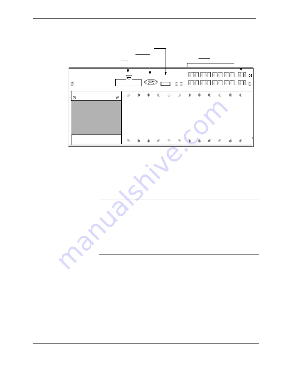
Hookup Connections for RACK2 

NET

2

CPU

2

Slot 1

Slot 2

Slot 3

Slot 4

6

5

7

8

9

10

11

12

13

14

15

16

A

B

C

D

E

F

G

H

P

W

R

COMPUTER

NET

24  Y  Z  G

MEMORY

EXPANSION

Compact Flash Memory

To PC (Optional, for setup only)

From Power Supply and To Cresnet Hub

To Network

Optional Network Power
Supplies or Internal
Connection

Future Use

Ethernet Card

2-Series and X-Generation Cards

(CNXCOM-2 not supported)


Establishing Communication with the RACK2 

Before uploading a program or performing diagnostic functions, you must connect 
the control system to the PC. This connection can be serial or (if an optional Z-Bus 
card is installed) it can be TCP/IP.  

Serial Connection 

NOTE:  

For laptops and other PCs without a built-in RS-232 port, Crestron 

recommends the use of PCMCIA cards, rather than USB-to-serial adapters. If a 
USB-to-serial adapter must be used, Crestron has tested the following devices with 
good results: 


Belkin (large model) F5U103 

 I/O 

Gear 

GUC232A 

 Keyspan 

USA-19QW 

 
Other models, even from the same manufacturer, may not yield the same results.


Connect the COMPUTER port on the control system to one of the COM ports 
(usually COM 1) on the PC. Use a straight-through RS-232 cable with a DB9 male 
connector on one end and a DB9 female connector on the other. Most commercially 
available cables are acceptable; they should have at least five pins for transmit, 
receive, ground, and hardware handshaking (pins 2, 3, 5, 7, and 8).  

Open the Crestron Viewport and click 

Setup | Communication Settings

 to display 

the “Port Settings” window. Then click 

RS-232

 as the connection type. 

The PC communication settings specified here should match the protocol that the 
RACK2 expects. The settings are as follows: 

• 

Port = COM 1 through COM 8. Select the correct COM port on the PC. 

Operation Guide – DOC. 5958 

2-Series Card Cage System: RACK2  

  21 

Summary of Contents for RACK2

Page 1: ...Crestron RACK2 2 Series Card Cage System Operations Guide ...

Page 2: ...n by the Technical Documentation department at Crestron Electronics Inc 15 Volvo Drive Rockleigh NJ 07647 1 888 CRESTRON All brand names product names and trademarks are the property of their respective owners 2003 Crestron Electronics Inc ...

Page 3: ...chpanel Projects via the RACK2 27 Updating the Operating System 27 Running Programs From Compact Flash 28 Other Compact Flash Related Functions 28 Advanced Console Commands 28 Programming 29 Programming with the Crestron AppBuilder 30 Programming with SIMPL Windows 30 Programming the LCD Screen 34 Problem Solving 39 Possible Problems with the Control System 39 Serial Communication Difficulties wit...

Page 4: ......

Page 5: ...ystem suitable for relatively large systems The RACK2 requires an external power supply CNPWS 75 not included Functional Summary Powered by 2 Series control engine 36 MB of internal memory 4 GB expansion slot for Type II compact flash and IBM Microdrive hard disk drive A multifunction LCD screen which can be programmed as a local panel interface displays front panel diagnostics system errors and m...

Page 6: ...t Future support will include USB USBII FireWire or disc drive array The dual port Ethernet card has a built in firewall which delivers the ultimate in security with on board Network Address Translator NAT and router functions It supports dynamic and static IP addressing and full duplex TCP IP and UDP IP and offers a WAN port for Internet and corporate wide communications and a LAN port for room a...

Page 7: ...power supply not included Total load factor for the RACK2 with CPU and NET2 is 12 watts 2 Requires CNPWS 75 not included Reset Buttons HWR Initiates system hardware reset SWR Program Restart Program Bypass LCD Screen Reverse mode yellow on black LCD backlight 2 lines up to 40 characters per line Environmental Temperature 41 to 113 F 5 to 45 C Environmental Humidity 10 to 90 RH non condensing Dimen...

Page 8: ...S 232 computer port in parallel with the port on the rear panel Standard LEDs PWR NET and ERR Local Area Network LEDs LAN A and B LNK and ACT Interface Control Card Slot LEDs 1 through 16 Two reset buttons A reverse green characters on a black background LCD screen with menu function and selection buttons RACK2 Front View 4 2 Series Card Cage System RACK2 Operations Guide DOC 5958 ...

Page 9: ...single RS 232 computer port in parallel with the port on the front panel Memory expansion slot on CPU2 Two banks of four Cresnet network mini connectors A through H with LED activity indicators on NET2 Two mini power supply connectors with LED power indicators on NET2 RACK2 Rear View Shown with optional Z Bus and Y Bus cards installed Operation Guide DOC 5958 2 Series Card Cage System RACK2 5 ...

Page 10: ... Series Card Cage System Crestron RACK2 RACK2 Physical View Front 17 28 in 43 89 cm 6 97 in 17 70 cm RACK2 Physical View Side 8 50 in 21 59 cm 6 2 Series Card Cage System RACK2 Operations Guide DOC 5958 ...

Page 11: ...or Ethernet devices NOTE Even though four slots are available only ONE C2ENET card may be installed in slot 1 The remaining three slots 2 3 and 4 are for future expansion The C2ENET 1 card provides one LAN port with an RJ 45 connector for connecting to the Ethernet network The C2ENET 2 card provides two LAN ports and a network address translator This allows a private sub network to be created with...

Page 12: ...red straight through Data Set Ready DSR and Data Terminal Ready DTR are not supported Standard DB9 Pin Assignments PIN ABBREVIATION DESCRIPTION 1 DCD Data Carrier Detect 2 RD Receive Data 3 TD Transmit Data 4 DTR Data Terminal Ready 5 SG Signal Ground 6 DSR Data Set Ready 7 RTS Request To Send 8 CTS Clear To Send 9 Ring Ring Indicator 1 2 3 4 5 Male DB9 Connector NET NET G Y 24 Z The master Cresne...

Page 13: ...ot operate RACK2 when NET2 is not installed The RACK2 system offers a great deal of data and power connection flexibility Control Connections You may choose to control the NET2 hub using the CPU2 or you may use an external control system Twisted pair wire is recommended for hookup NET2 CPU2 A B C D E F G H P W R NET 24 Y Z G 24 Y Z G 24 Y Z G 24 Y Z G 24 Y Z G 24 Y Z G 24 Y Z G 24 Y Z G 24 Y Z G G...

Page 14: ...to EXT to Apply 24 VDC to each group of four hub connectors All Grounds are Common If the power needed for a hub segment exceeds the power available from the power supply 75 watts max connected to the CPU2 remove the jumper from the 3 pin mini connector to disconnect the internal power supply then connect the Crestron 24 VDC regulated power supply 24 VDC to the EXT terminal and ground to the G ter...

Page 15: ... R button performs a system restart without loading the program refer to Troubleshooting Communications on page 23 Pressing it alone momentarily while the system is running restarts the program RACK2 Indicators There are 23 LED indicators on the front panel of the RACK2 and 10 LED indicators on the rear panel PWR This LED illuminates when the RACK2 receives power from the external power supply sol...

Page 16: ... the CPU2 or another source RACK2 LCD Screen and Buttons The front panel of the RACK2 incorporates a reverse mode yellow on black LCD screen as shown in the following illustration The screen contains two lines with up to 40 characters per line it is used to extend features and gain access to the system including the SIMPL program To the right of the screen there are four menu selection buttons The...

Page 17: ...card slots HWare the Cresnet devices detected Net the Ops version Ops and the communication settings Com is displayed While the COM menu is displayed press the or menu selection buttons to change the system baud rate NOTE The information within each of the commands displayed in the Info Menu may exceed the 40 characters permitted per line If this occurs use the two right most menu function buttons...

Page 18: ...ct Function 2 Series Error Log Save Error Log to File and follow the prompts The CLEAR button can to used to empty the error log and extinguish the ERR front panel LED A security message prompts the user to confirm the command NOTE The up and down menu selection buttons to the right of the LCD screen may be used in lieu of the NEXT and PREV menu function buttons NOTE Currently the Crestron Viewpor...

Page 19: ... top line Use the Dn down and Up selection buttons for hour and minute Min decremental or incremental changes respectively The AM PM selection button toggles between AM and PM Time Set Submenu COM This button allows the user to monitor the transmission and reception traffic on a COM type device and card that is active in the SIMPL Windows program that is loaded into the 2 Series control system Thi...

Page 20: ...rogram files SPLUS SIMPL module files USER User defined files MAILBOX User mailbox file CFØ The mounting point for the compact flash files CFØ DISPLAY Directory used to hold display files nvram The mounting point for NVRAM disk files Although the file system is case insensitive the case is preserved to maintain file checksums The compact flash directory only appears when the compact flash is inser...

Page 21: ...NOTE The new NVRAMDISK command available in CUZ files later than 3 030 will fail unless it can determine the amount of NVRAM used by the program to ensure that the NVRAM is not overwritten Programs compiled in SIMPL Windows version 2 04 11 or later can provide this information In the event of a failure of the NVRAMDISK command ensure that your program has been recompiled in an appropriate version ...

Page 22: ...cifications for CE marking and standards per EMC and Radiocommunications Compliance Labelling N11785 NOTE This device complies with part 15 of the FCC rules Operation is subject to the following two conditions 1 this device may not cause harmful interference and 2 this device must accept any interference received including interference that may cause undesired operation Setup Rack Mounting WARNING...

Page 23: ... SECURE WITH FOUR 6 32 SCREWS PER EAR SUPPLIED 2 Repeat step 1 of this procedure to attach the remaining ear to the right front side Network Wiring CAUTION Possible equipment damage if miswired NOTE When installing network wiring refer to the latest revision of the wiring diagram s appropriate to your specific system configuration available from the Downloads Product Manuals Wiring Diagrams sectio...

Page 24: ...nnection into the network connector and tighten the retaining screw Repeat the procedure for the other three network conductors Hardware Hookup Refer to the following hookup diagram Aside from connecting power last complete the connections in any order The serial cable to the PC may be attached to the DB9 connector of CPU2 on the rear panel or to the DB9 connector on the RACK2 front panel Use the ...

Page 25: ...SB to serial adapters If a USB to serial adapter must be used Crestron has tested the following devices with good results Belkin large model F5U103 I O Gear GUC232A Keyspan USA 19QW Other models even from the same manufacturer may not yield the same results Connect the COMPUTER port on the control system to one of the COM ports usually COM 1 on the PC Use a straight through RS 232 cable with a DB9...

Page 26: ... You must also have one optional Ethernet card C2ENET 1 or C2ENET 2 installed in Z Bus slot 1 1 Open Viewport and click Functions Set Control System IP Information 2 Enter the IP address IP mask and default router in the text fields All of these terms are explained in detail in the Crestron e Control Reference Guide Doc 6052 The latest version is available as a PDF on the Crestron website www cres...

Page 27: ...h Communications Find Rack This should display a window that gives the IP address and port number Troubleshooting Communications Use the following checklist if communication cannot be established with the RACK2 1 Verify that you are using the correct cables As described previously an RS 232 connection requires a straight through serial cable That is pin 1 on one end is connected to pin 1 on the ot...

Page 28: ...he following message Viewport Message RACK2 Control Console Changing to default Comm Specs 115200 N81 RTS CTS Switch to new settings Bypassing Program Load Release the SWR button d If communication still cannot be established Remove power from the control system Press and hold the SWR button on the front panel of the RACK2 Reapply power to the control system The Viewport console should display the...

Page 29: ...ogram check box will be enabled If it does contain SIMPL modules then the SIMPL program s check box will also be enabled Select one or both check boxes and then click Send Program to begin the transfer NOTE Unlike X Generation processors the 2 Series processor does not require a permanent memory image Also the 2 Series adds the ability to automatically retrieve the current program from the control...

Page 30: ...ions The RACK2 allots 2 5 MB of memory for user files such as web pages mailbox and the compiled SPZ file For detailed information refer to Uploading Web Pages in the Crestron e Control Reference Guide Doc 6052 The latest version is available as a PDF on the Crestron website www crestron com NOTE If you have a Compact Flash reader writer drive on your PC you can load HTML pages to a Compact Flash ...

Page 31: ...ly the files that are different from those that are currently stored in the panel Note that if any pages in the panel are not present in the project those pages will be deleted from the panel Additional choices include Do not send graphic files and Do not send sound files These are often very large files that need not be reloaded with every transfer Updating the Operating System As with all 2 Seri...

Page 32: ...grams files for processing A new SIMPL Windows command File Copy Output to Compact Flash copies a compiled SIMPL Windows program SPZ file to a compact flash reader writer on a PC Click Browse to locate the SPZ file select the drive letter of the CF reader writer from the drop down list Click OK to copy the file Advanced Console Commands The SIMPL Windows online help file provides a full listing of...

Page 33: ... directory is on compact flash gives the amount of space available on the compact flash If internal gives the amount left on internal flash TYPE Enables display of files residing on compact flash XGETFILE Enables retrieving a file from compact flash XPUTFILE Enables sending a file to compact flash Programming You create a control program for the RACK2 using Crestron programming tools Crestron Appl...

Page 34: ... graphical Windows based development tool for programming control systems The SIMPL Windows interface provides two workspaces the Configuration Manager for configuring the control system touchpanels and controlled network devices and Program Manager for designing the logic and functionality of the control system In addition you can use Crestron s powerful Viewport utility to accomplish multiple sy...

Page 35: ...E To view the list of supported devices expand the control system in the bottom pane of System Views and double click the C2Net Device slot or right click and select Add Item from the submenu Supported devices include network control modules lighting modules and a variety of Crestron wired touchpanels To add a device to the system expand the C2 Net Device slot and double click the desired Net ID o...

Page 36: ...ew of Programming Manager Front Panel Status Dual Ethernet Brightness The Front Panel Status Dual Ethernet Brightness symbol is a device extender for the C2I Front Panel slot of 2 Series control systems It is available only to control systems that accept the C2ENET 2 Ethernet card and which provide standard 2 Series error logging capabilities The Front Panel Status Dual Ethernet Brightness symbol ...

Page 37: ...e any ambiguous signals in the modules and minimize errors when the larger program is converted Converting SIMPL Modules 1 Open the SIMPL module you want to convert 2 Choose the 2 Series processor as the target by clicking the toolbar button as shown in the following illustration SIMPL Toolbar NOTE You can select both X and 2 Series as the targets so that the module will work for both control syst...

Page 38: ...hat are defined by the programmer Menu function buttons are assigned to different pages or objects The LCD screen has a 2x40 character display with six programmable buttons In Front Panel Editor pages are designed and added to the panel An example of the default page is shown after this paragraph Each front page is one screen 2x40 characters and can have as many objects as the physical size of the...

Page 39: ...anel Object window This example requires that headings be added to the page so choose Text Object from the Object Type area In the Inactive Text field enter Choose device and click OK The object is displayed on the panel Click on and drag the object to its desired location on the panel top row Add additional objects VCR DVD CD Lights and Volume to the page by double clicking in the screen area whe...

Page 40: ...age Double click on the first object play From the Digital Channel field in the Edit Panel Object window scroll down to or enter 1 In the Active Text field enter PLAY as the button s active text Therefore when the menu function button associated with digital channel 1 the VCR button is pressed the active text is displayed as a visual cue that the button is pressed Repeat the procedure for each of ...

Page 41: ...ote is used to denote a wildcard Front Panel Editor Window Front Panel Symbol A powerful tool to assist programmers in naming and routing signals for the LCD screen is the Synchronize Signals command While the panel appears on the PC screen select Panel Synchronize Signal Names to automatically name all the input and output signals for the front panel in the SIMPL Windows program To confirm the as...

Page 42: ...sample discussed in the previous sections utilizes only one of the object types available from the Edit Panel Object window shown below These object types are not new to Crestron programmers the same types are available in VT Pro e Object Type Area in the Edit Panel Object Window 38 2 Series Card Cage System RACK2 Operations Guide DOC 5958 ...

Page 43: ...at the cable is securely plugged into the NET connector Verify adequate Cresnet power Verify no shorts in wiring Verify that no two Net Devices have the same Net ID ERR LED illuminates Hardware or software failure hardware incompatibility with software definitions or programming error Verify that the hardware configuration matches software configuration Poll the network F4 from the Viewport check ...

Page 44: ...munication with the RACK2 on page 21 for more information 2 Open Viewport and select Setup Communication Settings to open the Port Settings window 3 In the window select RS 232 Connection Type 57600 Baud Rate N Parity 8 Data Bits and 1 Stop Bits and click OK 4 Power down the RACK2 5 While powering up the RACK2 press and hold ALT and K on the keyboard until the following text or similar appears in ...

Page 45: ...he latest version of Crestron NET2 Cresnet Hub Card Installation Guide Doc 5960 for NET2 replacement information Serial Communication Difficulties with Other Devices Connected to the Control System Passthrough Mode Passthrough mode allows data to pass directly from the COMPUTER port to the selected COM port on a Cresnet or Ethernet device such as ST COM or CEN COM effectively passing through the c...

Page 46: ...mands The user can SELECT the COM port shown on the top line or use NEXT or PREV appears after scrolling down from the top of the list to scroll through the entire list of all devices and cards that can be monitored Sample of COM Type Device or Card Listing NOTE The PREV command only appears after advancing past the first COM type device or card in the list NOTE The up and down menu selection butt...

Page 47: ...eception traffic is displayed in alternating sequence to facilitate diagnostics Depressing any of the six menu function buttons freezes the data information The up and down menu selection buttons to the right of the LCD screen may be used to advance or reverse the frozen data Compare the data to expected manufacturer s protocol for the communicating device NOTE Data in the freeze state is denoted ...

Page 48: ... www crestron com downloads software_updates asp for the latest version of firmware Not every product has a firmware upgrade but as Crestron improves functions adds new features and extends the capabilities of our products firmware upgrades are posted For questions regarding upgrade procedures contact Crestron customer service Future Updates As Crestron improves functions adds new features and ext...

Page 49: ...mands data or instructions from or to another computer b for local campus or wide area network internet or web hosting services or c pursuant to any rental sharing or service bureau arrangement The Software is designed as a software development and customization tool As such Crestron cannot and does not guarantee any results of use of the Software or that the Software will operate error free and Y...

Page 50: ...ninety 90 days from the date of receipt and b that any hardware accompanying the Software will be subject to its own limited warranty as stated in its accompanying written material Crestron shall at its option repair or replace or refund the license fee for any Software found defective by Crestron if notified by you within the warranty period The foregoing remedy shall be your exclusive remedy for...

Page 51: ...ps are not covered This warranty extends to products purchased directly from CRESTRON or an authorized CRESTRON dealer Purchasers should inquire of the dealer regarding the nature and extent of the dealer s warranty if any CRESTRON shall not be liable to honor the terms of this warranty if the product has been used in any application other than that for which it was intended or if it has been subj...

Page 52: ...Crestron Electronics Inc Operations Guide DOC 5958 15 Volvo Drive Rockleigh NJ 07647 06 03 Tel 888 CRESTRON Fax 201 767 7576 Specifications subject to www crestron com change without notice ...

Reviews: