background image

2-6 The Pentium® II Processor

Step 2: To install the heat sink support

Before you install the heat sink support, please verify if your 
Pentium II processor is the Intel boxed processor or the OEM 
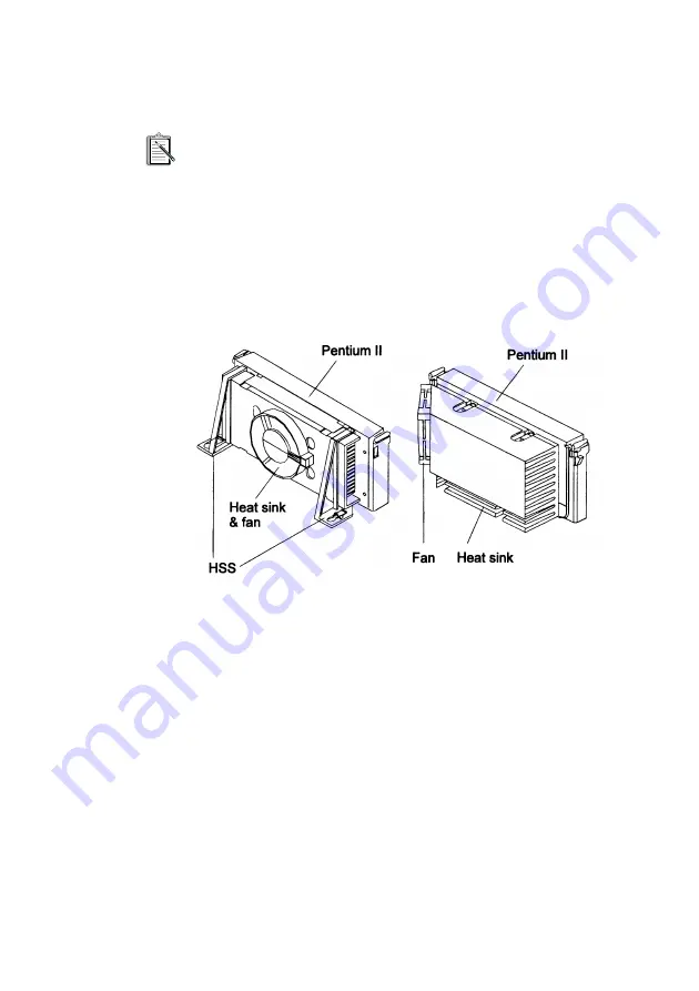
type Pentium II processor with active heat sink (see Figure 
2-9).  If you have an Intel boxed processor, ignore this section.  
Intel boxed processor kits include their own heat sink support 
accessories and installation manuals.  Refer to Intel’s 
installation manual if you are using an Intel boxed processor.

Figure 2-9:   The two types of Pentium II processors.

The Intel boxed processor

The OEM type processor with 
active heat sink

Summary of Contents for Blaster PC M001

Page 1: ...TM M001 Motherboard...

Page 2: ...nd by the terms and conditions of this Agreement 9 Limitations on Using Copying and Modifying the Software Except to the extent expressly permitted by this Agreement or by the laws of the jurisdiction...

Page 3: ...ii...

Page 4: ...against the law to copy the software on any other medium except as specifically allowed in the license agreement The licensee may make one copy of the software for backup purposes Copyright 1998 by Cr...

Page 5: ...y one or more of the following measures q Reorient or relocate the receiving antenna q Increase the distance between the equipment and receiver q Connect the equipment to an outlet on a circuit differ...

Page 6: ...m II processor 2 8 3 The Celeron Processor About the Celeron Processor 3 1 Installing the Hardware for the Celeron Processor 3 2 Components of the Celeron Processor s retention mechanism 3 3 Step 1 To...

Page 7: ...uration 6 1 BIOS Settings 6 2 To change BIOS settings in CMOS 6 2 The CMOS Setup Utility Menu 6 3 Standard CMOS Setup 6 5 BIOS Features Setup 6 8 Chipset Features Setup 6 11 Power Management Setup 6 1...

Page 8: ...brief introduction on the Intel Pentium II processor and shows you how to mount the processor on the motherboard Chapter 3 The Celeron Processor Gives you a brief introduction on the Intel Celeron pr...

Page 9: ...le 0 1 Text conventions Text Elements Use bold Text that must be entered exactly as it appears italic Title of a book or a placeholder A placeholder represents information that you must provide UPPERC...

Page 10: ...rt AGP slot a high performance hardware interface for graphics intensive applications such as 3D applications The AGP slot is independent of the Peripheral Component Interconnect PCI bus and is design...

Page 11: ...r Intel Celeron processor 266 300 and 333MHz Versatile Memory Supports Four DIMM sockets that support 168 pin 3 3V SDRAM memory modules with maximum possible memory size of up to 1GB Configurable supp...

Page 12: ...vides licensed Award V4 51PG BIOS on Flash Electrically Erasable Programmable Read Only Memory EEPROM Supports Green PC DMI and bundled with NCR SCSI BIOS Board Size ATX form factor 305mm x 220mm Adva...

Page 13: ...seconds the system will go into the Soft off mode Use the CMOS Setup Utility to specify the mode you want For details see the section Power Management Setup on page 6 14 Wake ON LAN Automatic switchi...

Page 14: ...The M001 Motherboard 1 5 Figure 1 1 The M001 motherboard...

Page 15: ...software In addition the Pentium II processor delivers new levels of performance for advanced media and communications software including powerful realistic graphics and imaging capabilities video con...

Page 16: ...shows the front rear and top views of the Pentium II processor without heat sink mounted The Pentium II processor requires the Retention Mechanism RM and the Heat Sink Support HSS to hold the base pro...

Page 17: ...s bare Components of the Pentium II Processor s retention mechanism The Retention Mechanism RM consists of the following parts Retention Mechanism RM A plastic guide with captive nuts that hold the SE...

Page 18: ...Figure 2 4 2 Mount the RM onto Slot 1 Make sure that the square cut mark of the RM has the same orientation as Pin 1 of Slot 1 See Figure 2 5 3 Insert four RM attachment pins through the RM to secure...

Page 19: ...stic support bar mounted to the motherboard under the ATX heat sink HSS Pins Plastic pins inserted through the HSS base to secure it to the motherboard Two pins are required for each assembly HSS Top...

Page 20: ...II processor with active heat sink see Figure 2 9 If you have an Intel boxed processor ignore this section Intel boxed processor kits include their own heat sink support accessories and installation m...

Page 21: ...ing holes on the motherboard Note that one peg is larger than the other see Figure 2 10 3 Push the pegs firmly into the holes to mount the HSS base onto the motherboard 4 Insert the HSS pins through t...

Page 22: ...e processor down firmly with even pressure on both sides of the top until it is seated 5 Push the latches on the processor outward until they click into place in the RM The latches must lock into plac...

Page 23: ...m II processor and the Celeron processor are the latest additions to the P6 processor family They combine the architectural advances in the Pentium Pro processor with the instruction set extensions of...

Page 24: ...SEPP technology Figure 3 1 shows the Celeron processor with and without heat sink mounted Before you proceed do the following 1 Switch off the computer 2 Remove the motherboard from the chassis 3 Plac...

Page 25: ...r If you should need help with the mechanism please contact your dealer The RM package consists of 2 sets of components Each set consists of one RM two post pins and two lock pins q Retention Mechanis...

Page 26: ...that the two guides face each other 3 Insert four post pins through the RM to secure it to the motherboard 4 Insert four lock pins through the post pins to lock the RM to the motherboard Components of...

Page 27: ...n clip must be located on the non primary side of the processor see Figure 3 5 The side of the clip which touches the substrate surface on the processor is covered with a mylar insulator This insulato...

Page 28: ...between the HS retention clip and the heat sink Do not bend or apply pressure directly to the SEPP 7 Use a non metallic bar stock or screwdriver to push the remaining two clip legs into the heat sink...

Page 29: ...that all the feet of the clip are fully inserted and the clip is firmly attached to the heat sink see Figure 2 21 9 Proceed to Step 3 To mount the Celeron processor Figure 3 7 Verifying that the clip...

Page 30: ...M sockets on the motherboard 2 Align the processor with the RM and slowly slide the processor into it see Figure 3 8 3 Push the processor down firmly with even pressure on both sides until it is seate...

Page 31: ...ack Panel Connectors q Other Connectors Front Panel Connectors Figure 4 1 below shows the positions of the front panel connectors on your motherboard Hardware Reset Connector J29 A 2 pin hardware rese...

Page 32: ...nnector J28 A 4 pin IDE drive LED cable is attached to this connector The LED lights up when an IDE device is active ATX Power On Off Switch Connector JP15 PWR_ON A 2 pin momentary type switch is atta...

Page 33: ...the motherboard Plug the parallel port device cable into this connector USB1 USB2 Port Connectors Two female USB connectors are located at the rear of the board Plug USB devices into these connectors...

Page 34: ...A Remote controller to the COM2 serial port of the host computer Use the CMOS Setup Utility to enable the infrared receiver For details see the section Integrated Peripherals on page 6 20 Figure 4 4 s...

Page 35: ...wake the connected system through the LAN card Enhanced IDE and Floppy connectors The motherboard is shipped with one 40 pin ribbon cable for IDE hard disk drives and one 34 pin ribbon cable for flopp...

Page 36: ...per when holding the motherboard with the keyboard connector away from yourself Table 5 1 below shows the jumper conventions used in this manual To close a jumper Place a jumper cap over the two jumpe...

Page 37: ...you do not need to change the jumper settings you can leave them as the factory default Do not change the jumper settings unless you are an advanced user Changing the jumper settings incorrectly may...

Page 38: ...Clock ratio multiplier Set the jumper according to the multiplier that you want see Table 5 3 Table 5 3 shows all the multipliers that the motherboard supports Table 5 2 Settings for System Clock and...

Page 39: ...tting you select the specific system clock CPU external clock frequency within the 66 MHz to 112 MHz range through BIOS settings for details see Chipset Features Setup on page 11 For 66 MHz based Pent...

Page 40: ...ble This can cause the motherboard to stop functioning properly In such cases you need to clear the CMOS record by using jumper JP6 To clear the CMOS 1 Switch off the computer 2 Remove the jumper cap...

Page 41: ...2 V By setting up jumper J9 the motherboard can use either 5 V or 12 V to flash the EEPROM with new system BIOS files when necessary Table 5 5 Jumper Settings for CMOS Clear CMOS JP6 Jumper Clear CMOS...

Page 42: ...MB and 256 MB 3 3 V single or double sided SDRAM DIMM The four DIMM sockets are arranged in four banks of one socket each Each bank provides a 64 72 bit wide data path The M001 provides optional data...

Page 43: ...memory check press the Delete key The CMOS Setup Utility menu similar to Figure 6 1 on page 6 3 appears If you did not respond in time restart your system by pressing the Reset button on your computer...

Page 44: ...of the menu options Table 6 2 The CMOS Setup Utility menu options This Option Allows You To Do This Standard CMOS Setup Set the date time disk drive video display and error handling BIOS Features Setu...

Page 45: ...s allows you to limit access to the system and setup or to limit access to the setup only IDE HDD Auto Detection Automatically detect and configure IDE hard disk drives HDD in your system Save Exit Se...

Page 46: ...OS Setup utility PU the Page Up key PD the Page Down key the plus key the minus key Standard CMOS Setup Display this screen if you want to set the date and time of the system clock This screen also al...

Page 47: ...herwise your hard disk will not work properly For IDE hard disk drives set the entries to Auto under TYPE and the system will configure the hard disk drives automatically when it is switched on You ca...

Page 48: ...e number of heads Drive A Drive B Specifies the types of floppy disk drive A or drive B that has been installed in the system Video Selects the type s of adapter used for the primary system monitor Th...

Page 49: ...e primary hard disk drive and warn of any attempt to write to it If an attempt is detected the BIOS will halt the system and the following warning message will appear In this situation restart your sy...

Page 50: ...20 Option Allows you to specify how the gate A20 is handled The gate A20 is a device used to address memory above 1 MB Initially the gate A20 was handled via a pin on the keyboard Today while keyboard...

Page 51: ...enabled if there is a MPEG ISA card installed in the system and disabled if there is no MPEG ISA card installed in the system OS Select For DRAM 64 MB If you are using the OS 2 operating system and yo...

Page 52: ...and apply the pre determined optimal chipset parameters If it is disabled chipset parameters revert to CMOS setup information DRAM Speed Selection Sets the EDO DRAM Read Write timings that the system...

Page 53: ...ut poses the danger of system errors if programs are written to this memory area Video BIOS Cacheable Allows the user to specify the system BIOS C000h F7FFFh area as cacheable or non cacheable The Ena...

Page 54: ...e a programmable delayed completion mechanism to meet the required target latencies AGP Aperture Size MB Specifies the maximum amount in MB of system memory an AGP display card can use to store 3D tex...

Page 55: ...mode after a brief period of system idle time Min Saving is similar to Max Saving except the period of the system idle time is longer Disabled disables the power saving feature User Defined allows yo...

Page 56: ...e Doze the video display gets turned off after system enters Doze mode N A there will be no display shut off MODEM Use IRQ This item defines the IRQ line that the modem can use The available settings...

Page 57: ...ing the button for less than 4 seconds will place the system in Suspend mode and pressing the button for more than 4 seconds will shut the system off CPUFAN Off In Suspend This item defines the CPU fa...

Page 58: ...s enabled the system will power on itself from power off when the activity of LAN M001 supports Wake ON LAN function with Intel LAN cards only Table 6 8 The PnP PCI Configuration Screen items Item Des...

Page 59: ...se in your system By default Setup assumes that your controller is an ISA device rather than a PCI controller If you have equipped your system with a PCI controller changing this setting allows you to...

Page 60: ...or will be reflected on the system device under windows 95 Device Manager MS IRQ Routing Table Specifies whether the BIOS IRQ Routing Table is enabled or disabled PCI Latency Timer The PCI Latency Tim...

Page 61: ...ripherals Display this screen if you want to configure the IDE and floppy controllers and other onboard ports You can also configure the USB USB Keyboard Support and infrared UR2 Mode and UR2 Duplex M...

Page 62: ...ettings 0 1 2 3 and 4 defined for the manual mode and one setting Auto for the automatic mode The default setting is Auto IDE Primary Master UDMA UDMA stands for Ultra DMA On this motherboard Intel PI...

Page 63: ...ler you may choose to disable the secondary controller USB Keyboard Support Enables or disables the USB keyboard support KBC Input Clock Sets the input clock to onboard keyboard controller KBC The set...

Page 64: ...arallel port mode The settings are SPP Standard Parallel Port EPP Enhanced Parallel Port ECP Extended Capabilities Port and EPP ECP ECP Mode Use DMA Specifies the DMA Direct Memory Access channel when...

Page 65: ...restrict who can change critical Setup values Enter Password Type a password up to eight characters long and press Enter The password typed now will clear any previously entered password from CMOS mem...

Page 66: ...ers assume the entire cost of all necessary servicing repair or correction This warranty gives you specific legal rights and you may also have other rights which vary from country state to country sta...

Page 67: ...Printed in Singapore...

Reviews: