11
B-4.3) Overload Protection:
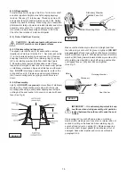
Current sensing overloads must be provided in the pump
control panel and should be properly sized for the full load
current of the pump. Three normally closed (N/C) thermal
sensors wired in series (one per phase) are embedded in
the motor windings and will detect excessive heat in the
event an overload condition occurs. Upon sensing the
over temperature condition, the normally closed contact in
the sensors will open and turn the pump off when wired in
series with the motor contactor control circuit. The thermal
sensor leads marked P1 and P2 MUST be connected in
series with the pilot circuit of the magnetic motor controller
located in the control panel so that the thermostat will open
the circuit before dangerous temperatures are reached.
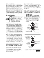
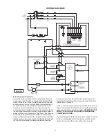
A manual momentary start switch is required to prevent
the automatic restarting of the motor when the thermostat
resets, refer to Figure 4.
In the event of an over temperature condition, the source of
this condition should be determined and rectified before the
pump is put back into normal operation.
DO NOT LET THE
PUMP CYCLE OR RUN IF AN OVER TEMPERATURE
CONDITION OCCURS!
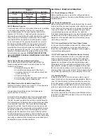
If current through the temperature sensor exceeds the values
listed, an intermediate control circuit relay must be used to
reduce the current or the sensor will not work properly.
WIRING DIAGRAM
FIGURE 4
Summary of Contents for DEMING 7365N-X54-95-30N
Page 18: ...18 FIGURE 9 Vortex Enclosed CROSS SECTIONS FIGURE 10 ...
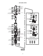
Page 19: ...19 EXPLODED VIEWS FIGURE 11 ...
Page 22: ...22 Notes ...


