


EnglIsh
8
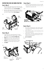
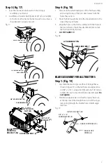
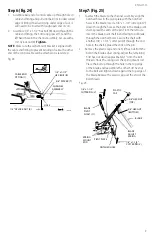
Step 2: (fig. 20)
1. Insert the round hook end of the angle lock spring up
through the hole in the spring mount bracket.
2. Insert the angle lock bars down through the slot in the
channel. Underneath the channel, place a 1" long
spacer (U) on each side of the angle lock bars and
insert a 1/4" x 3-1/4" bolt (A) through the channel,
angle lock bars and the spacers. Secure the bolt with a
1/4" nylock nut (K).
3.
Tighten
so that the lock bars can pivot freely.
4. At this time
Tighten
the 3/8" carriage bolt and hex nut
previously assembled in
"sTEP 1: (sEE FIgURE 19)"
nOTE:
When the angle lock bars are pulled back in slot, the
pivot plate should unlock and be free to pivot to the right or
left position.
1/4" x 3-1/4"
HEX BOLT (A)
1" SPACERS (U)
1/4" NYLOCK
NUT (K)
PIVOT
PLATE
ANGLE
LOCK
SPRING
SPRING
MOUNT
BRACKET
CHANNEL
Fig. 20
Step 3: (fig. 21)
1. Using a hammer, assemble a 3/8" palnut (S) onto one
end of the spring mount rod. Insert the other end of
the spring mount rod through the pivot plate using
the rear set of holes. Support the assembled end
of the spring mount rod on a block of wood, and
assemble the remaining palnut onto the other end
of the rod.
3/8" PALNUT (S)
PIVOT
PLATE
SPRING
MOUNT
ROD (5)
3/8" PALNUT (S)
Fig. 21
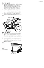
Step 4: (fig. 22)
1. Assemble a 3/8" x 1-1/4" carriage bolt (E) through the
square hole in the Cable Mount Bracket and through
the square hole in the angle lock bars. (The carriage
bolts should face in opposite directions.) Using pliers
hold the cable mount bracket in positions. Angling
down towards the L.H. hole in the channel as shown
in Figure 22. Secure with a 3/8" nylock nut (M).
Tighten.
Refer to the figure for the correct angle for
the cable mount bracket.
3/8" x 1-1/4"
CARRIAGE BOLT (E)
3/8" NYLOCK
NUT (M)
ALIGN CABLE
MOUNT BRACKET
WITH L.H. HOLE (2)
ANGLE
LOCK
BARS
FRONT
Fig. 22
Step 5: (fig. 23)
1. Assemble one 5/16" jam nut (J) approximately 3/4"
onto threaded end of control cable that has no rubber
cap or preassembled nuts. Assemble threaded cable
end through round hole in cable mount bracket and
secure with another 5/16" jam nut (J).
Tighten.
nOTE:
Some adjustment of jam nuts may be required after
blade assembly is completed.
CHANNEL ASSEMBLY
5/16" JAM
NUT (J)
5/16" JAM
NUT (J)
CABLE MOUNT
BRACKET (2)
REAR
3/4"
Fig. 23


