background image

17

POOLDENS

COSMOGAS

4 - OPERATION

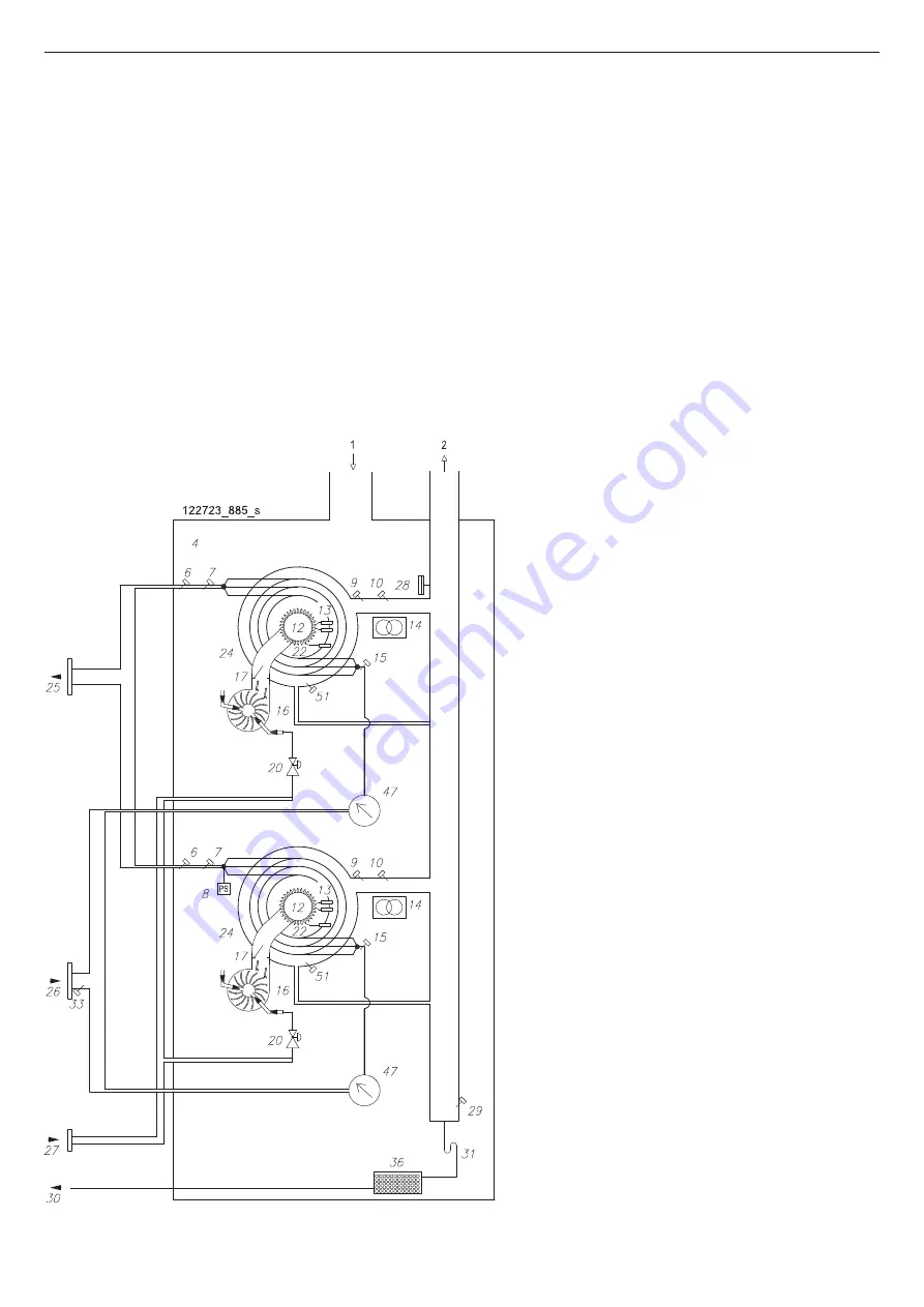
Figure 4-2 - Hydraulic operating diagram for models 100T, 115T and 140T 

Figure 4-2 Key:

1 - Air intake

2 - Exhaust gases outlet

4 - Sealed chamber

6 - Water outlet temperature safety thermostat

7 - Water outlet temperature sensor

8 - Water pressure gauge

9 - Exhaust gases temperature sensor

10 - Exhaust gases temperature safety fuse

12 - Pre-mixed burner

13 - Ignition electrodes

14 - Sparks generator

15 - Water inlet temperature sensor

16 - Fan

17 - Back flue preventer valve

20 - Gas valve

22 - Detection electrode

24 - VRC heat exchanger

25 - Water outlet

26 - Water inlet

27 - Gas inlet

28 - Pressure switch against outlet blockage

29 - Condensate level sensor

30 - Condensate outlet

31 - Condensate outlet siphon

33 - Pool return temperature sensor

36 - Condensate neutraliser

47 - Water flow rate gauge

51 - Primary heat exchanger temperature fuse

Summary of Contents for POOLDENS 100T

Page 1: ...62403761 R03 03 12 2020_UK INSTALLATION USE AND MAINTENANCE MANUAL GAS CONDENSING POOL HEATERS POOLDENS ...

Page 2: ......

Page 3: ...amples of installation 28 9 3 Safety relief valve 30 9 4 Delivery and return 31 9 5 Water supply 31 9 5 1 Chemical balancing 31 9 5 2 Disinfectant 31 9 5 3 TAC Total Alkalinity Certificate 32 9 6 Characteristic curve of head losses 33 10 INSTALLATION Disposal of condensate 34 10 1 Condensate outlet 34 11 INSTALLATION Electrical connections 35 11 1 Electrical connections details 35 11 1 1 Connectin...

Page 4: ...stics lockouts Loc 63 15 10 2 Diagnostics errors Err 65 16 MAINTENANCE 67 16 1 General warnings 67 16 1 1 Gas leak check 67 16 1 2 Check good order of air intake and flue gas outlet ducts 67 16 1 3 Check ignition and detection electrodes 67 16 1 4 Check intervention of safety thermostat 67 16 2 Dismantling of cover and access to internal components 68 16 3 Dismantling of burner fan assembly 68 16 ...

Page 5: ...ture reference If the appliance has to be replaced or if you have to move and leave behind the appliance for another user always make sure that this brochure is left for the new user and or installer Any eventual optional extras or kits added later must be Cosmogas originals The manufacturer bears no contractual or non contractual responsibility for damage caused by errors in the installation or u...

Page 6: ...ls and jacuzzis 1 GENERAL SAFETY WARNINGS 1 1 National installation laws and regulations Rules regarding the prevention of fires issued by the fire service Ministerial Decree of 01 12 75 Law of 09 01 91 n 10 as amended Presidential Decree of 26 08 93 n 412 Ministerial Decree of 12 04 96 Presidential Decree of 21 12 99 n 551 Legislative Decree of 19 08 05 n 192 Legislative Decree of 29 12 06 n 311 ...

Page 7: ... treated so that any substances that are dangerous for the environment can be removed and disposed of safely This will enable all the raw materials to be recycled The user is responsible for getting rid of the appliance at the end of its life delivering it to Recycling Centres run by the local authority or city hygiene companies or when he she buys a new appliance giving the product that is replac...

Page 8: ...r outlet pipe 8 9 Heat exchanger 10 11 12 Stopper not present 13 Water pressure sensor present in burner 1 MASTER 14 Sparks generator 15 Ignition cables 16 Water flow rate gauge 17 18 Water inlet pipe 3 MAIN COMPONENTS Figure 3 1 Internal components of models 34T 60T 70T 100T 115T 140T 180T 210T and 280T 18 9 7 15 16 14 5 12 13 1 3 4 2 020009 01 037 ...

Page 9: ...rature sensor 27 LH ignition electrode 28 RH ignition electrode 29 30 31 Flue gases check valve 32 Check valve magnet 33 Check valve sensor 3 MAIN COMPONENTS Figure 3 2 Internal components of models 34T 60T 70T 100T 115T 140T 180T 210T and 280T 7 21 19 27 28 23 26 18 25 020009 01 038 32 33 31 25 020009 01 028_a ...

Page 10: ...utlet 13 Board 885 IF on request 14 Electrical connections 15 16 17 Control panel 18 19 Top front casing 20 Burner 1 command and control board 21 Bottom front casing 24 Pressure switch against outlet blockage 25 Electrical connections board 26 Pool return temperature sensor 35 36 Water outlet 37 Water inlet 38 Drain valve 3 MAIN COMPONENTS Figure 3 3 Internal components of models 34T 60T and 70T 5...

Page 11: ...ector 29 Exhaust gases temperature sensor blue connector 1006 30 Exhaust gases outlet manifold 31 Water inlet pipe 32 33 Condensate level sensor 34 39 Primary heat exchanger temperature fuse 3 MAIN COMPONENTS Figure 3 4 Internal components of models 34T 60T and 70T BURNER 1 Master 31 22 33 30 39 28 29 27 23 020014 01 024 ...

Page 12: ... 885 IF on request 14 Electrical connections 15 16 17 Control panel 18 Burner 2 command and control board 19 Top front casing 20 Burner 1 command and control board 21 Bottom front casing 24 Pressure switch against outlet blockage 25 Electrical connections board 26 Pool return temperature sensor 35 36 Water outlet 37 Water inlet 38 Drain valve 3 MAIN COMPONENTS Figure 3 5 Internal components of mod...

Page 13: ...ust gases temperature sensor blue connector 1006 30 Exhaust gases outlet manifold 31 Water inlet pipe 32 33 Condensate level sensor 34 39 Primary heat exchanger temperature fuse 3 MAIN COMPONENTS Figure 3 6 Internal components of models 100T 115T and 140T BURNER 2 BURNER 1 Master 31 31 22 33 30 39 39 28 28 29 29 27 27 23 020029 01 003 ...

Page 14: ...electrical wires 11 Air intake filter 12 Exhaust gases outlet 13 Board 885 IF on request 14 Electrical connections 15 16 17 Control panel 18 Burner 2 3 4 command and control board 19 Top front casing 20 Burner 1 command and control board 21 Bottom front casing 24 Pressure switch against outlet blockage 25 Electrical connections board 26 Pool return temperature sensor 35 36 Water outlet 37 Water in...

Page 15: ...4 22 Top cover 23 General ON OFF switch 27 Fan cover 28 Exhaust gases temperature safety fuse red connector 29 Exhaust gases temperature sensor blue connector 1006 30 Exhaust gases outlet manifold 31 Water inlet pipe 32 33 Condensate level sensor 34 39 Primary heat exchanger temperature fuse 31 31 31 31 22 28 28 29 33 29 28 30 39 39 39 39 28 29 29 27 27 27 27 23 020030 01 002 ...

Page 16: ...lectrodes 14 Sparks generator 15 Water inlet temperature sensor 16 Fan 17 Back flue preventer valve 20 Gas valve 22 Detection electrode 24 VRC heat exchanger 25 Water outlet 26 Water inlet 27 Gas inlet 28 Pressure switch against outlet blockage 29 Condensate level sensor 30 Condensate outlet 31 Condensate outlet siphon 33 Pool return temperature sensor 36 Condensate neutraliser 47 Water flow rate ...

Page 17: ...ust gases temperature safety fuse 12 Pre mixed burner 13 Ignition electrodes 14 Sparks generator 15 Water inlet temperature sensor 16 Fan 17 Back flue preventer valve 20 Gas valve 22 Detection electrode 24 VRC heat exchanger 25 Water outlet 26 Water inlet 27 Gas inlet 28 Pressure switch against outlet blockage 29 Condensate level sensor 30 Condensate outlet 31 Condensate outlet siphon 33 Pool retu...

Page 18: ...ety fuse 12 Pre mixed burner 13 Ignition electrodes 14 Sparks generator 15 Water inlet temperature sensor 16 Fan 17 Back flue preventer valve 20 Gas valve 22 Detection electrode 23 Inlet and outlet manifold 24 VRC heat exchanger 25 Water outlet 26 Water inlet 27 Gas inlet 28 Pressure switch against outlet blockage 29 Condensate level sensor 30 Condensate outlet 31 Condensate outlet siphon 33 Pool ...

Page 19: ...use 12 Pre mixed burner 13 Ignition electrodes 14 Sparks generator 15 Water inlet temperature sensor 16 Fan 17 Back flue preventer valve 20 Gas valve 22 Detection electrode 23 Inlet and outlet manifold 24 VRC heat exchanger 25 Water outlet 26 Water inlet 27 Gas inlet 28 Pressure switch against outlet blockage 29 Condensate level sensor 30 Condensate outlet 31 Condensate outlet siphon 33 Pool retur...

Page 20: ...e to connect it to any pump In figure 9 1 the pool circuit pump is detail 1 When choosing this pump the designer must check the system features as well as the details in section 9 6 4 1 3 Types of system The following types of system can be created with this appliance System solely for the production of hot water for swimming pools or jacuzzis see figure 9 1 4 2 Precautions for installation For th...

Page 21: ...d cause serious injury to people death or enormous material damage 5 INSTALLATION Place of installation WARNING If installed in rooms with a thin floor a resonating noise could be generated The installation of noise reduction elements is required WARNING The appliance must only be installed on a solid floor which takes its weight and is level Before installation carefully wash out the system to re...

Page 22: ...e of any outlet fans ceiling fans dryers compressors air heating units etc that might take air away from the appliance WARNING Extractors or similar devices for the removal of air from the heating unit might reduce the ventilation required for combustion and or cause low pressure in the ventilation system Escapes of exhaust gases from the ventilation system in an occupied habitable room can cause ...

Page 23: ...ge fixed to the pallet for transportation Be careful when opening it take the cardboard box off by lifting it upwards after detaching it from the pallet 6 1 3 Lifting the appliance For convenience during installation a rod is provided detail A in figure 6 1 which enables the appliance to be lifted remove the top cover as in section 16 2 hook lifting cables B in figure 6 1 onto the rod A in figure ...

Page 24: ...ce it is necessary to leave free spaces around the appliance as shown in figures 7 1 and 7 2 The dimensions and connection centre space distances for the appliances are shown in figures 8 1 and 8 2 Figure 7 1 Minimum distances to be observed for models 34T 60T 70T 100T 115T and 140T Figure 7 2 Minimum distances to be observed for models 180T 210T and 280T ...

Page 25: ...ce distances Figure 8 1 Dimensions and centre space distances of attachments for models 34T 60T 70T 100T 115T and 140T References in figure 8 3 Figure 8 2 Dimensions and centre space distances of attachments for models 180T 210T and 280T References in figure 8 3 ...

Page 26: ...0 mm 1 1 4 28 mm Connections and flanges are not factory fitted Air intake in room do not obstruct and do not add any connection Figure 8 3 Table of diameters of connections in figures 8 1 and 8 2 C B E A D A 020013 01 015 Figure 8 4 Assembly of flanges and reductions on threaded connections for hot water outlet cold water inlet and gas WARNING The hot water outlet cold water inlet and gas connect...

Page 27: ...ately before the appliance in order to allow the gas supply to be interrupted WARNING It is forbidden to supply the appliance with a type of gas other than those anticipated The appliance requires a water flow rate at an adequate pressure for it to operate The flow of water must go from the appliance to the spa or swimming pool without any component being able to interrupt the flow Should the flow...

Page 28: ...afety valve responsibility of the installer 12 Gas inlet 14 Main electrical switch Hot 230 Vac 50Hz Neutral Ground External Safety Device External Safety Device Heating Pump Line max 3A Heating Pump Neutral max 3A Ground DHW Pump Line max 3A DHW Pump Neutral max 3A Ground Local Pump Line max 3A Local Pump Neutral max 3A Ground Header sensor HS Header sensor HS Room thermostat Room thermostat Tank ...

Page 29: ...s pump 14 Main electrical switch Hot 230 Vac 50Hz Neutral Ground External Safety Device External Safety Device Heating Pump Line max 3A Heating Pump Neutral max 3A Ground DHW Pump Line max 3A DHW Pump Neutral max 3A Ground Local Pump Line max 3A Local Pump Neutral max 3A Ground Header sensor HS Header sensor HS Room thermostat Room thermostat Tank sensor Tank sensor Outdoor sensor OS Outdoor senso...

Page 30: ...take into account that the valve intervention pressure cannot be higher than the maximum allowable pressure of the appliance This value can be found in the table in section 17 WARNING Isolation devices must not be installed between the appliance and the safety valve WARNING It is forbidden to obstruct the opening of the safety drain valve with any object WARNING The safety drain valve must be orie...

Page 31: ... be used up in the process of destroying bacteria algae and other oxidisable materials The remaining disinfectant is called residual chlorine or bromine residue The level of residual disinfectant in the swimming pool water can be determined with test kits available at a swimming pool supplies shop It is necessary to maintain a residual disinfectant level that is sufficient to ensure the continuous...

Page 32: ...ou have found the right stability you can do the check once a month Contact your valued dealer to buy a suitable kit Parameters to check in content of water Parameters to be checked Ideal values Frequency of check Free chlorine From 0 6 to 1 0 mg l Daily Combined chlorine Lower than 0 4 mg l Daily pH From 7 2 to 7 6 pH Daily Cyanuric acid From 25 to 50 mg l Weekly Total alkalinity From 100 to 140 ...

Page 33: ...e does not have a circulation pump For the size of the pump to be used the designer must consider the system s hydraulic resistances and the hydraulic resistances of the appliance itself refer to figure 9 4 9 INSTALLATION Plumbing Figure 9 4 Key A models 34T 60T and 70T B models 100T and 115T C models 140T D models 180T and 210T E models 280T ...

Page 34: ...oming back into the room In particular the condensate disposal system must be done through a pipe with an internal diameter equal to or greater than 13 mm be installed in such a way as to avoid the liquid freezing so pay attention to any external sections it cannot be discharged into gutters or drainpipes be at a constant slope towards the discharge point avoid high points which could put the duct...

Page 35: ...icinity of the appliance This switch must have a contact opening distance of at least 3 mm as expected by current regulations on the subject Respect the polarity between live and neutral when connecting the appliance Make sure that the water central heating and gas system pipes are not used as earths for the electrical or telephone system These pipes are not at all suitable for this purpose furthe...

Page 36: ...can be controlled via the 0 10 Vdc signal according to the rules shown in figure 11 2 MODBUS type dialogue on request Board 885 IF allows the appliance to be controlled through MODBUS dialogue proceeding as shown in the instructions supplied on request Maximum delivery temperature Par 3017 Minimum delivery temperature Par 3018 Hysteresis of ON OFF Voltage 11 1 3 Alarm contact The alarm contact onl...

Page 37: ...37 POOLDENS COSMOGAS 11 INSTALLATION Electrical connections Figure 11 3 Electrical connections Example of system shown in figure 9 1 ...

Page 38: ...et type B23 or B23P and will therefore take in air for combustion from the room in which it is located Therefore all precautions regarding ventilation of rooms set by national and or local regulations must be followed During operation especially in winter because of the high performance it is possible that white smoke could emerge from the appliance s flue gas outlet This is purely a natural pheno...

Page 39: ...igned to make all the liquid produced by a single appliance drain out If more than one appliance is installed each should be provided with its own condensate outlet The flue gas outlet system can be extended up to a maximum distance as shown in section 17 Each 90 bend has a loss equivalent to that reported in section 17 WARNING The flue gas outlet terminal must be correctly protected against the e...

Page 40: ...w B for fastening the rods to the framework of the external cover figure 13 15 8 Attach the cover AB using screws C to the framework of the external cover as shown in figure 13 16 9 Put on the covers AA and AC in the direction shown in figure 13 19 and fasten them to the structure with screws C first removing the pre cut discs present figures 13 17 and 13 18 It is also possible depending on the ty...

Page 41: ... 002 H J A 62610111 005 K K 62610111 006 J K 62610111 007 G 62610111 009 Figure 13 1 Figure 13 2 Figure 13 3 Figure 13 4 Figure 13 5 Figure 13 6 Figure 13 7 Figure 13 8 Figure 13 9 Figure 13 10 Figure 13 11 J I 62610111 042 F U 62610110 011 F 62610110 012 13 INSTALLATION External cover ...

Page 42: ...110 006 AB C 62610110 004 C Y AC X AA 62610110 005 R B R S B B 62610110 007 C C AD AD 62610110 008 E A 62610111 012 Q B 62610111 013 62610111 023 Figure 13 12 Figure 13 14 Figure 13 16 Figure 13 17 Figure 13 18 Figure 13 19 Figure 13 20 Figure 13 21 Figure 13 22 62610111 039 Figure 13 13 Figure 13 15 ...

Page 43: ...Figure 13 23 M W L O N P W 62610111 044 D D D 62610111 030 Figure 13 26 Figure 13 27 G AE 62610111 021 Figure 13 25 Figure 13 24 B B 62610112 006 Figure 13 28 Z 62610111 032 B AS AR AR J AS 62610112 009 AN 62610112 007 B 62610112 010 Figure 13 29 Figure 13 30 Figure 13 31 ...

Page 44: ...etal sheets AC and AD in figure 13 54 respectively in front of figure 13 51 and behind figure 13 52 the previously assembled metal sheets in the direction shown by the arrows Then put in screws B as in figure 13 53 WARNING the metal sheets AC and AD include holes of different diameters see figure 13 54 For correct assembly position them in the ways described in point 10 11 Remove the pre cut discs...

Page 45: ...2610111 002 H J A 62610111 005 K K 62610111 006 J K 62610111 007 G 62610111 009 Figure 13 32 Figure 13 33 Figure 13 34 Figure 13 35 Figure 13 36 Figure 13 37 Figure 13 39 Figure 13 40 Figure 13 41 Figure 13 42 J I 62610111 042 U F 62610111 045 F 62610111 046 J H A 62610111 004 Figure 13 38 ...

Page 46: ...018 B 62610111 019 Figure 13 48 Figure 13 49 Figure 13 50 Figure 13 51 Figure 13 52 Figure 13 53 V 62610111 040 Figure 13 47 E A 62610111 012 Q B 62610111 013 62610111 023 Figure 13 43 Figure 13 45 Figure 13 54 Figure 13 56 62610111 039 Figure 13 44 Q A B 62610111 011 Q 62610111 010 Figure 13 46 Ø 3 16 mm AD AC Ø 5 00 mm 62610111 020 Figure 13 55 ...

Page 47: ... 62610111 024 C C AF AG R B 62610111 025 AH 62610111 026 B C S R B 62610111 027 Figure 13 57 Figure 13 58 Figure 13 59 Figure 13 60 Figure 13 62 S 62610112 011 Figure 13 61 C AL AM C AM AL 62610111 028 G AE 62610111 021 Figure 13 63 Figure 13 64 B B 62610112 006 ...

Page 48: ...nal cover Z 62610111 032 Figure 13 67 Figure 13 69 M W L O N P W 62610111 044 D D D 62610111 030 AP Z AN Z 62610111 031 Figure 13 68 Figure 13 70 B AS AR AR J AS 62610112 009 AN 62610112 007 B 62610112 010 Figure 13 71 Figure 13 65 Figure 13 66 ...

Page 49: ...illed with water to create the shutter that can prevent flue gases from escaping from pipe 5 in figures 3 3 3 5 and 3 7 To this end proceed as follows refer to Figure 14 1 1 undo and remove stopper A shown in the figure 2 insert a rubber tube into hole S and at the other end of the tube position a funnel 3 slowly pour about 5 litres of water through the funnel 4 reassemble everything in reverse or...

Page 50: ...e seal test at a pressure of not more than 50 mbar if the test of the gas system has to be carried out at pressures greater than 50 mbar turn the cock located immediately up stream from the appliance to isolate it from the system In figure 8 4 you can check the position of the gas connection The sections of tubing making up the gas adduction system must always ensure a supply of gas that is suffic...

Page 51: ...gasket H in figure 14 2 9 Replace fork A in the locking housing 10 Tighten joint H in figure 14 2 11 Open the gas supply valve 12 Check that there are no leaks from joint H in figure 14 2 WARNING Carry out the gas seal test only with a soap water solution The use of naked flames is absolutely forbidden 13 Turn on the appliance by moving the main switch to ON detail T in figure 15 1 14 Completely u...

Page 52: ...S A Connector from burner 1 MASTER B Connector from display C Connector from burner 2 D Connector from burner 3 E Connector from burner 4 Figure 14 5 Burners position Burner 2 Burner 1 Master Burner 3 Burner 4 14 START UP ...

Page 53: ...esent as shown below 4 Carry out the conversion in Burner 3 following points 1 to 16 of section 14 4 After converting Burner 3 continue with Burner 4 if present as shown below 5 Carry out the conversion in Burner 4 following points 1 to 16 of section 14 4 After converting all the Burners continue as shown below 6 Check the gas inlet pressure as shown in section 14 7 7 Check the appliance power as ...

Page 54: ... 8 4 to 8 6 from 8 4 to 8 6 O2 Methane gas G20 at maximum power from 5 0 to 5 4 from 5 2 to 5 6 O2 Methane gas G20 at minimum power from 5 7 to 5 9 from 5 7 to 5 9 CO2 Methane gas G25 at maximum power N A from 8 5 to 9 1 CO2 Methane gas G25 at minimum power N A from 8 3 to 8 5 O2 Methane gas G25 at maximum power N A from 4 7 to 5 1 O2 Methane gas G25 at minimum power N A from 5 5 to 5 7 CO2 LPG ga...

Page 55: ...e temperature set is higher than the output temperature and that the system is in the right conditions to disperse the heat generated 8 Set parameter 2200at HIGH in models 60T and 70T use parameter 2010 Now the burners will operate at maximum power for 20 minutes 9 with the appliance at maximum capacity check that the gas supply pressure does not fall below 10 mbar 100 mmH2 O If the pressure is lo...

Page 56: ...utes for the CO2 to stabilise 6 Insert the sensor to read the value of CO2 in point F shown in figure 14 9 7 Compare the value of CO2 detected with that shown in table 14 8 make sure you read the value for the type of gas being used If the value of CO2 is not that shown in table 14 8 you must correct it using screw E in figure 14 10 Using a 2 5 mm six sided spanner turn the screw clockwise to redu...

Page 57: ...on burner 3 and 2204 on burner 4 14 Close the combustion analysis hole in figure 12 2 with a suitable stopper F as shown in the manufacturer s instructions for the outlet pipe WARNING Once stopper F is in position with the appliance at maximum power check there are no leaks of exhaust gases that could cause damage 14 9 Check appliance power The appliance s air gas mixture ratio is set at the facto...

Page 58: ...different parameters within the different menus N Heating temperature or indicator of values assumed by the different parameters O Unit of measurement of temperature displayed Q Appliance lockout R Button to scroll and change parameter values S Button to scroll and change parameter values T On Off switch 15 1 Water pressure check 15 1 1 Water pressure check If the pressure inside the circuit falls...

Page 59: ... be adjusted using buttons or see figure 15 1 The temperature is measured in the return manifold The temperature of the water input into the swimming pool is influenced by the flow rate and temperature of the water in the by pass circuit 15 6 Anti frost protection During the wintertime if there are no problems with freezing it is possible to continue using the filter pump continuously even if the ...

Page 60: ...1055 Burner 1 Number of failed ignitions of burner no 1056 Burner 1 Number of hours worked h x 10 1057 Burner 1 Number of hours worked on domestic hot water with puffer tank h x 10 1059 Time interval between the last two lockouts Loc 1 value in minutes 2 value in hours 3 value in days 4 value in weeks 1060 Time interval between the last two errors Err 1062 Burner 1 Water flow rate l min 1101 Multi...

Page 61: ...on as shown in section 16 8 WARNING To make it easier to replace the command and control board it is essential to make a note of any variation made to the parameters in the Personalised values column in the table below The following parameters can be changed or examined in this menu 15 USE Parameter Description of parameter U M Settings field Factory value Person alised values 2001 Minimum power l...

Page 62: ... temp burner ignition C from 0 to 20 2 2106 Multi burner delta temp burner switch off C from 0 to 20 2 2107 Multi burner maximum increase in temp compared to that calculated C from 0 to 20 20 2108 Multi burner maximum reduction in temp compared to that calculated C from 0 to 20 10 2109 Multi burner Next burner ignition from 1 to 100 70 2110 Multi burner Next burner switch off from 1 to 100 10 2111...

Page 63: ...e good order of the electrical connections between gas valve and control board A If the electrical connections are interrupted reset them B If the connections are in good order try to replace the gas valve or the control board Loc 4 Gas valve relay doesn t close Check the good order of the electrical connections between gas valve and control board A If the electrical connections are interrupted re...

Page 64: ...ch circuit or external safety devices A Check the connection to the external safety device B Check intervention of exhaust gases differential pressure switch C Check for any possible blockage of flue gas outlet A Check external safety devices connected to terminals 103 and 104 B Check the pressure switch against the flue gas outlet blockage and if necessary replace it C Get rid of any possible blo...

Page 65: ...Low water pressure error Check the system s pressure and if necessary increase it If the pressure detected is higher than that in parameter 3022 replace the pressure gauge Err 60 Exhaust gases high temperature error A Check the combustion output of the burner the error is flagged up against output must be above that required by regulations B Check that the exhaust gases temperature sen sor s resis...

Page 66: ...hes the graph in section 16 13 If the sensor doesn t match it must be replaced Err 87 RESET button error RESET button pressed too many times in 60 seconds Err 93 Appliance selection error Check list of parameters 3000 section 18 Err 107 Software error inside control board Replace the command and control board Err 108 Software error inside control board Replace the command and control board Err 109...

Page 67: ...the appliance WARNING Do not carry out these checks where there are naked flames 16 1 2 Check good order of air intake and flue gas outlet ducts 1 Check whether the air intake and flue gas outlet ducts have any blockages signs of corrosion physical damage water marks or signs of rust 2 Check that the intake grills and flue gas outlet terminals fitted outside do not contain any residue and are clea...

Page 68: ...plugs 4 dismantle air manifold A in Figure 16 3 by turning it clockwise and then taking it out leftwards 5 undo junction H in figure 16 4 paying attention to the gasket in the joint 6 with the help of a flat head screwdriver remove spring A in Figure 16 4 7 remove the electric plug from the gas valve 8 remove the gas valve by lifting it upwards taking care with O ring L see figure 16 4 9 Undo the ...

Page 69: ... DO NOT use a metal brush Only use a brush with bristles made of nylon or a similar material 5 using an extractor suck up the unburnt residue found inside the combustion chamber H 6 with the same extractor clean the surface of the burner and around the electrodes 7 reassemble the parts in reverse order 8 turn on the gas cock 9 restore the electric power supply 10 check that there are no gas leaks ...

Page 70: ...assembly R H B A C T S 020009 01 039 020009 01 032 WARNING The gasket ensures the combustion chamber is sealed If the gasket is damaged DO NOT reuse it it must be replaced along with the burner assembly Consult the manufacturer regarding replacement GASKET BURNER ASSEMBLY ...

Page 71: ... is good to use sliding calipers to respect the tolerances given in Figure 16 7 A Left hand ignition electrode B Right hand ignition electrode C Detection electrode R H N C A E Q B F S L G M D 020022 01 009 A Fixing screw B Washer C Heat insulation device E Heat insulation device E White heat insulation device G Burner H Gasket L Ignition electrodes M Screws N Detection electrode Q White heat insu...

Page 72: ...ry six months or year depending on how they are controlled by the local regulations in force The neutralising contents of the box must be replaced when the level of pH falls below the level required by the regulations in force The permitted acidity level goes from pH 5 5 to 9 5 To replace the neutralising agent do the following 1 Follow the steps of section 16 2 to take off cover E in figure 16 1 ...

Page 73: ...Connector for dialogue Burner 3 Only in models 180T 210T and 280T E Connector for dialogue Burner 4 Only in model 280T 1 Disconnect the electric power supply from the appliance 2 Follow the steps of section 16 2 to access the internal components 3 Disconnect terminal B coming from the display from terminal A coming from Burner 1 Master 4 Connect terminal B to terminal C D or E depending on which b...

Page 74: ...m Burner 1 Master 4 Disconnect all the other connectors from Burner 1 Master s control board 5 Remove the control board of Burner 1 Master from the appliance A 020009 01 010_a ON OFF SELECTOR SWITCH S4 6 Follow points 3 to 5 to remove the control board from the burner located lowest down 7 Fit the board in place of that of Burner 1 Master 8 Restore all the connections to the new Burner 1 Master bo...

Page 75: ...75 POOLDENS COSMOGAS 16 MAINTENANCE Figure 16 12 Setting parameters 3001 3050 and selectors S4 Models 280T Models 180T 210T Models 100T 115T 140T Models 34T 60T 70T ...

Page 76: ...t minimum power b Ign to force the burner or all the burners at ignition power c HIgH to force the burner or all the burners at maximum power 4 To end forcing return parameter 2010 2200 for multi burner models to the 0FF value and press the RESET button WARNING If during forcing the power delivered by the appliance is much higher than the power absorbed by the system the appliance continually goes...

Page 77: ...mperature sensors are positioned on the exchanger body The electrical resistance existing between the two contacts of the sensor must correspond to what is shown in Figure 16 13 The temperature sensors are 1001 1002 1006 and 1007 Figure 16 13 Water sensors curve 16 MAINTENANCE ...

Page 78: ...78 POOLDENS COSMOGAS 16 14 Multi wire wiring diagram for models 34T 60T and 70T Figure 16 14 Multi wire wiring diagram part 1 continues on next page 16 MAINTENANCE ...

Page 79: ...79 POOLDENS COSMOGAS 16 MAINTENANCE Figure 16 14 Multi wire wiring diagram part 2 continued from previous page ...

Page 80: ...80 POOLDENS COSMOGAS 16 MAINTENANCE Figure 16 15 Multi wire wiring diagram part 1 continues on next page 16 15 Multi wire wiring diagram for models 100T 115T 140T 180T 210T and 280T ...

Page 81: ...81 POOLDENS COSMOGAS 16 MAINTENANCE Continues Figure 16 15 Multi wire wiring diagram part 2 continued from previous page ...

Page 82: ...82 POOLDENS COSMOGAS 16 MAINTENANCE Figure 16 15 Multi wire wiring diagram part 3 continued from previous page ...

Page 83: ...alve 22 Detection electrode 28 Exhaust gases differential pressure switch 29 Condensate level sensor 32 General ON OFF switch 34 Display 35 Board 885 IF on request Fuse F1 5x20 3A 47 Water flow rate sensor 48 Two way motorised valve not present 50 Primary heat exchanger temperature fuse 51 Electrical connections board Fuse F1 5x20 10A Fuse F2 5x20 10A Fuse F3 5x20 3A Fuse F4 5x20 3A Fuse F6 5x20 3...

Page 84: ...37 37 37 37 Gas supply minimum pressure G20 mbar 17 17 17 17 G25 mbar N A 20 20 20 G30 mbar N A 25 25 25 G31 mbar 25 25 25 25 Gas supply maximum pressure G20 mbar 25 25 25 25 G25 mbar N A 30 30 30 G30 mbar N A 35 35 35 G31 mbar 45 45 45 45 Primary exchanger water content l 4 6 4 6 5 7 9 2 Minimum operating water flow rate l h 4500 4500 4500 9000 Delivery temperature adjustment field C 20 50 20 50 ...

Page 85: ...98 1 12 22 14 80 18 30 22 20 29 61 14 22 17 22 21 32 25 83 34 43 9 11 11 03 13 66 16 55 22 06 8 97 10 87 13 50 16 30 21 73 20 20 20 20 20 20 20 20 20 20 30 30 30 30 30 37 37 37 37 37 17 17 17 17 17 20 20 20 20 20 25 25 25 25 25 25 25 25 25 25 25 25 25 25 25 30 30 30 30 30 35 35 35 35 35 45 45 45 45 45 9 2 11 4 17 1 17 1 22 8 9000 9000 13500 13500 18000 20 50 20 50 20 50 20 50 20 50 95 95 95 95 95 ...

Page 86: ...et C 80 80 80 80 Minimum temperature of flue gases at appliance outlet C 30 30 30 30 Maximum output of flue gases g s 16 2 27 2 31 9 45 3 Maximum output of flue gases at minimum power g s 5 8 5 9 7 1 5 9 Hydraulic head available at outlet Pa 110 110 110 110 Maximum temperature of the combustion agent air C 40 40 40 40 Maximum CO2 content in the combustion agent air 0 9 0 9 0 9 0 9 Maximum fumes te...

Page 87: ... 2 5 8 5 4 5 8 5 4 5 8 5 4 5 8 5 4 5 8 5 4 5 6 4 9 5 6 4 9 5 6 4 9 5 6 4 9 5 6 4 9 6 2 5 1 6 2 5 1 6 2 5 1 6 2 5 1 6 2 5 1 6 0 5 4 6 0 5 4 6 0 5 4 6 0 5 4 6 0 5 4 10 10 10 10 10 80 80 80 80 80 30 30 30 30 30 52 8 63 9 78 9 95 8 127 8 5 9 7 1 7 1 7 1 7 1 110 110 110 110 110 40 40 40 40 40 0 9 0 9 0 9 0 9 0 9 95 95 95 95 95 110 110 110 110 110 14 5 17 6 21 8 26 3 35 1 4 4 4 4 4 0 5 50 0 5 50 0 5 50 ...

Page 88: ...N A 3 N A 0 0 0 3012 DHW operation mode 0 only central heating 1 storage tank with puffer 2 storagetankwiththermostat 3 N A 4 N A 5 N A 0 0 0 3013 Reset Err 115 EnAb Enabled DISA Disabled Enab Enab Enab 3015 Climate regulation maximum central heating delivery temperature this parameter is overwritten by parameter 3017 from 20 C to 90 C 82 C N D N D 3016 Climate regulation minimum central heating d...

Page 89: ...arameters in the other burners you need to connect the display to them as shown in section 16 8 The forced menu allows the appliance to be set according to the system to be provided Setting is done by adjusting the parameters available shown in the table To access the forced menu proceed as follows 1 Turn off electricity to the appliance by moving the main switch to OFF 2 Hold down both the RESET ...

Page 90: ...ion Press and release the RESET key Hold down the reset key for 2 seconds Hold down the reset key for 5 seconds Hold down at the same time for a time in seconds indicated by the number the RESET and q keys q Press and release the q key p Press and release the p key ...

Page 91: ...parameters see section 15 8 Installer menu parameters see section 15 9 Installer menu parameters see section 15 9 Access to user menu see section 15 8 Access to installer menu see section 15 9 Return to normal operation Return to normal operation Figure 19 1 Diagram of command menu 19 DIAGRAM OF COMMAND MENU ...

Page 92: ...tion output g Daily consumption of electrical energy kWh g Annual consumption of electrical energy kWh g Daily consumption of fuel kWh g Annual consumption of fuel GJ h Water heater thermostat temperature adjustment C 60 60 i Level of sound power inside LWA dB 70 70 j The water heater can only operate during slack times NO NO k any eventual specific precautions to take during assembly installation...

Page 93: ...6 0 19 0 35 0 37 0 36 0 39 0 51 0 54 42 77 81 79 85 112 118 27 850 53 069 53 258 53 336 53 158 105 905 106 693 22 42 42 42 42 84 84 60 60 60 60 60 60 60 70 70 70 70 70 70 70 NO NO NO NO NO NO NO Read the instructions for the installation use and maintenance of the product N A N A N A N A N A N A N A 27 27 27 27 27 27 27 20 PRODUCT FICHE ...

Page 94: ...ng the standards EN 26 2015 and the Low Voltage Directive 2014 35 UE applying the standards EN 60335 1 2012 A11 2014 and EN 60335 2 102 2016 and the Electro Magnetic Compatibility Directive 2014 30 UE applying the standards EN 55014 1 2019 and EN 55014 2 2016 Energy labeling regulation 2017 1369 UE Eco friendly design directive 2009 125 CE Directive on the use of dangerous substances 2011 65 UE Mo...

Page 95: ......

Page 96: ...COSMOGAS s r l Via L da Vinci 16 47014 MELDOLA FC ITALY info cosmogas com www cosmogas com ...

Reviews: