7
‐
4
A
particular
blade
may
have
teeth
which
are
too
hard
at
the
tips,
causing
them
to
break
off
in
the
material.
This
is
most
likely
to
happen
as
a
result
of
chips
wedging
together
in
the
cut.
A
broken
tooth
in
the
material
can
easily
cause
dulling
on
one
side
of
the
entire
blade
before
it
is
dislodged
from
the
cut.
Blade
Speed
and
Feed:
Blade
speed
is
generally
limited
by
vibration
and
the
ability
to
keep
the
blade
sufficiently
cool
to
avoid
dulling
the
teeth.
A
blade
which
is
running
fast
and
taking
a
very
light
cut
will
dull
quickly
because
the
tips
of
the
teeth
will
overheat
from
the
rubbing
action.
If,
however,
we
force
the
blade
teeth
deeper
into
the
material,
the
blade
will
be
less
sensitive
to
heat,
because
the
teeth
are
cutting
more
and
rubbing
less.
Tooth
Form
and
Spacing:
The
selection
of
a
tooth
form
generally
is
determined
by
the
material
to
be
cut.
There
are
three
general
factors
to
consider:
tooth
form,
style
or
shape
of
the
teeth;
tooth
spacing,
the
number
of
teeth
to
the
inch;
and
tooth
set,
which
provides
clearance
for
the
body
of
the
blade.
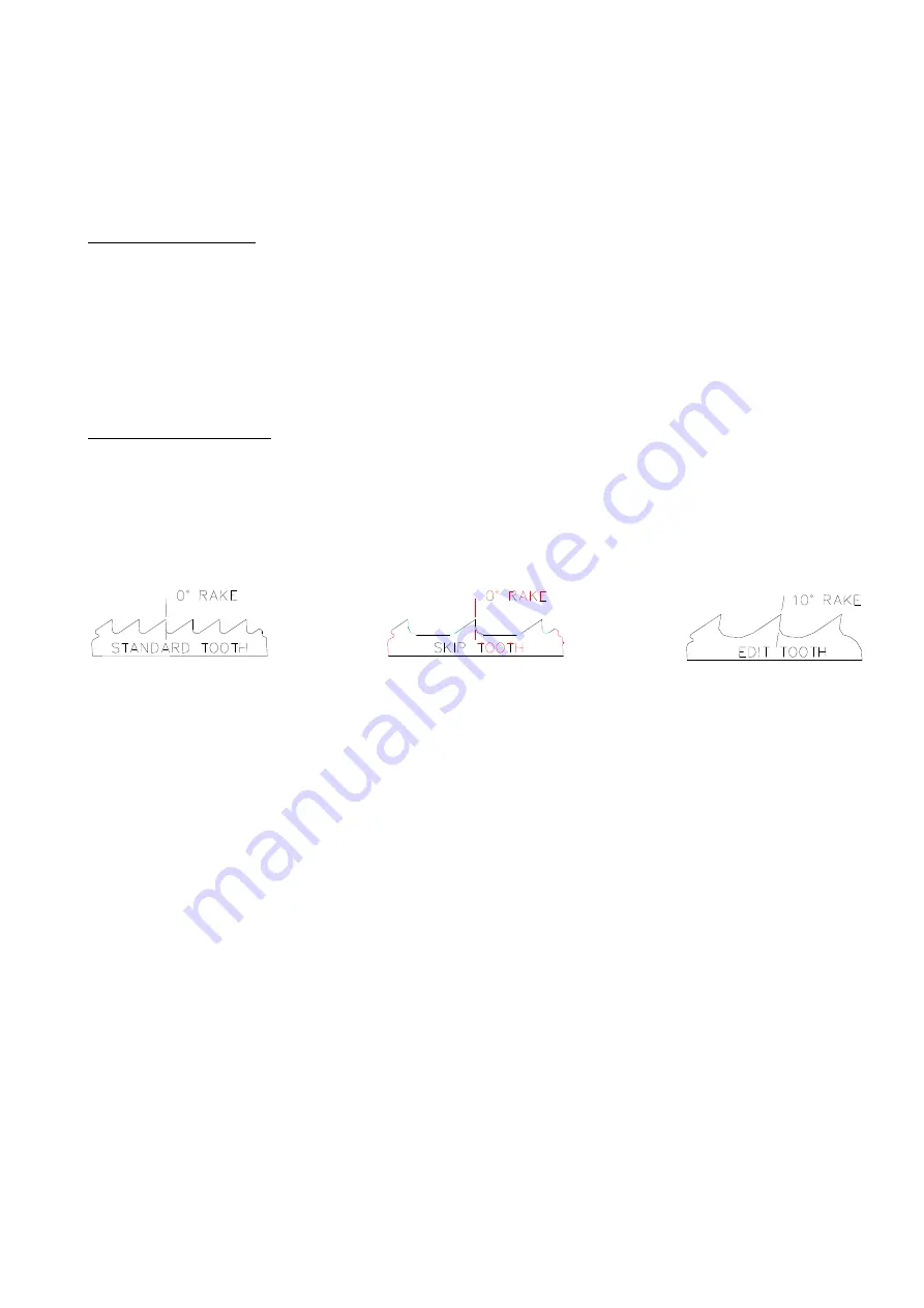
Three
styles
of
tooth
are
shown
in
Fig.
7.4
below:
Fig.
7.4
Three
styles
of
tooth
SOME
SAWING
PRACTICES
Saw
Pitch
Selection
Sawing
“Rules
of
Thumb”:
1.
The
thinner
the
stock,
the
finer
the
saw
pitch
2.
The
thicker
the
stock,
the
coarser
the
saw
pitch
3.
The
more
difficult
the
stock,
the
finer
the
saw
pitch
4.
The
softer
the
material
,
the
coarser
the
saw
pitch
Always
have
at
least
three
teeth
in
contact
with
the
material
being
cut.
Material
Size
and
Saw
Pitch
Anytime
during
the
cutting
operation,
at
least
three
teeth
must
be
in
contact
with
the
material
being
cut.
Figure
7.5
shows
some
sawing
practices:
Summary of Contents for SH-710LDM
Page 13: ...1 4 Illustration Safety Fence CE model only Safety Fence 右護欄 Safety Fence 左護欄 ...
Page 15: ...1 6 Illustration Emergency Stop Emergency Stop 急停按鈕 ...
Page 19: ...1 10 Illustration Safety Labels ...
Page 23: ...2 3 MACHINE PARTS IDENTIFICATION ...
Page 24: ...2 4 FLOOR PLAN Machine top view Machine front view ...
Page 25: ...2 5 Right view Drawing ...
Page 65: ...5 2 Fig 5 1 Control panel layout ...
Page 66: ...5 3 Fig 5 2 Circuit board layout ...
Page 67: ...5 4 Fig 5 3 Power supply layout ...
Page 68: ...5 5 Fig 5 4 PLC I O layout ...
Page 69: ...5 6 Fig 5 5 Main circuit layout CE ...
Page 70: ...5 7 Fig 5 6 Safety circuit layout CE ...
Page 71: ...5 8 Fig 5 7 DC24V layout CE ...
Page 72: ...5 9 Fig 5 8 Inverter layout CE ...
Page 73: ...5 10 Fig 5 9 PLC layout CE ...
Page 74: ...5 11 Fig 5 10 PLC IN1 layout CE ...
Page 75: ...5 12 Fig 5 11 PLC IN2 layout CE ...
Page 76: ...5 13 Fig 5 12 PLC IN3 layout CE ...
Page 77: ...5 14 Fig 5 13 PLC IN4 layout CE ...
Page 78: ...5 15 Fig 5 14 PLC OUT1 layout CE ...
Page 79: ...5 16 Fig 5 15 PLC OUT2 layout CE ...
Page 80: ...5 17 Fig 5 16 PLC OUT3 layout CE ...
Page 81: ...5 18 Fig 5 17 Control panel layout CE ...
Page 82: ...6 1 Section 6 HYDRAULIC SYSTEM HYDRAULIC DIAGRAMS ...
Page 83: ...6 2 Fig 6 1 Hydraulic layout ...
Page 123: ...10 23 ...


