4
‐
18
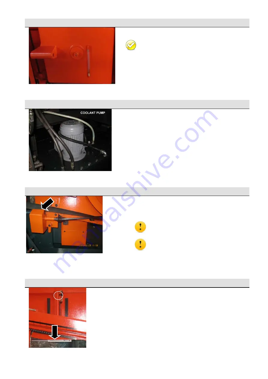
Gear
reducer
The
specially
designed
gear
reducer
can
work
toward
your
preset
blade
speed
and
torque.
Please
refer
to
Chapter
8
for
information
on
maintenance.
Coolant
Pump
The
coolant
pump
supplies
coolant
to
cool
off
cutting
temperatures
during
cutting.
Also,
it
can
be
used
to
wash
off
chips.
Wire
Brush
The
wire
brush
is
driven
by
the
belt
to
rotate
at
the
same
speed
as
the
blade
motor.
It
removes
the
metal
chips
on
the
saw
blade
teeth
so
that
blade
life
can
be
extended.
Keep
hands
away
from
the
transmission
shaft
and
the
brush
while
the
wire
brush
is
running.
Turn
off
the
hydraulic
motor
or
the
main
power
switch
before
performing
maintenance
or
cleaning
on
the
wire
brush
drive
system.
Hydraulic
top
clamp
device
The
device
is
installed
on
the
saw
bow.
Used
for
cutting
bundles,
the
top
clamp
will
hold
the
material
tightly
so
as
to
avoid
material
sliding
during
cutting.
Use
the
adjustment
valve
to
adjust
its
speed
during
clamping/unclamping.
When
the
vise
moves,
the
top
clamp
will
act
in
synchronization.
Gear reducer
Adjustment
Valve
Top
clamp
Summary of Contents for SH-710LDM
Page 13: ...1 4 Illustration Safety Fence CE model only Safety Fence 右護欄 Safety Fence 左護欄 ...
Page 15: ...1 6 Illustration Emergency Stop Emergency Stop 急停按鈕 ...
Page 19: ...1 10 Illustration Safety Labels ...
Page 23: ...2 3 MACHINE PARTS IDENTIFICATION ...
Page 24: ...2 4 FLOOR PLAN Machine top view Machine front view ...
Page 25: ...2 5 Right view Drawing ...
Page 65: ...5 2 Fig 5 1 Control panel layout ...
Page 66: ...5 3 Fig 5 2 Circuit board layout ...
Page 67: ...5 4 Fig 5 3 Power supply layout ...
Page 68: ...5 5 Fig 5 4 PLC I O layout ...
Page 69: ...5 6 Fig 5 5 Main circuit layout CE ...
Page 70: ...5 7 Fig 5 6 Safety circuit layout CE ...
Page 71: ...5 8 Fig 5 7 DC24V layout CE ...
Page 72: ...5 9 Fig 5 8 Inverter layout CE ...
Page 73: ...5 10 Fig 5 9 PLC layout CE ...
Page 74: ...5 11 Fig 5 10 PLC IN1 layout CE ...
Page 75: ...5 12 Fig 5 11 PLC IN2 layout CE ...
Page 76: ...5 13 Fig 5 12 PLC IN3 layout CE ...
Page 77: ...5 14 Fig 5 13 PLC IN4 layout CE ...
Page 78: ...5 15 Fig 5 14 PLC OUT1 layout CE ...
Page 79: ...5 16 Fig 5 15 PLC OUT2 layout CE ...
Page 80: ...5 17 Fig 5 16 PLC OUT3 layout CE ...
Page 81: ...5 18 Fig 5 17 Control panel layout CE ...
Page 82: ...6 1 Section 6 HYDRAULIC SYSTEM HYDRAULIC DIAGRAMS ...
Page 83: ...6 2 Fig 6 1 Hydraulic layout ...
Page 123: ...10 23 ...


