background image


A15ES 


© Corroventa Avfuktning AB 

2022.05 

40 (67) 


Filter replacement 


Filter replacement is performed as follows:  

1.


Stop the machine by pushing Stop on the control panel so that the machine enters the 
automatic cooling sequence. 

2.


Allow the cooling sequence to finish and wait until the count down on the display has 
disappeared and the fans have stopped. 

3.


Turn off the mains power switch by turning it anti clockwise to position 0. 

4.


Open the filter hatches and remove the old filters.  

5.


Clean the filter compartments, preferably with a vacuum cleaner, so that the dust and dirt 
that have fallen off the filters is removed. If left in the machine, the dust and dirt will clog the 
new filters 

6.


Insert the new filters and close and lock the filter hatches. 

7.


Push Resume to have the machine start up with the same settings and adjustments as 
before. Preferably wait by the machine a few minutes to see that the operation is normal 
and that there are no alarms presented on the control panel. 


Service and repair work including cleaning 


For service and repair, at all times, the power must be disconnected from the 
machine. Stop the machine and let it cool down. Proceed by turning off the mains 
power switch and remove the power cable from the power intake. Ensure that no 
other personnel reconnect power to the machine while the work is ongoing.


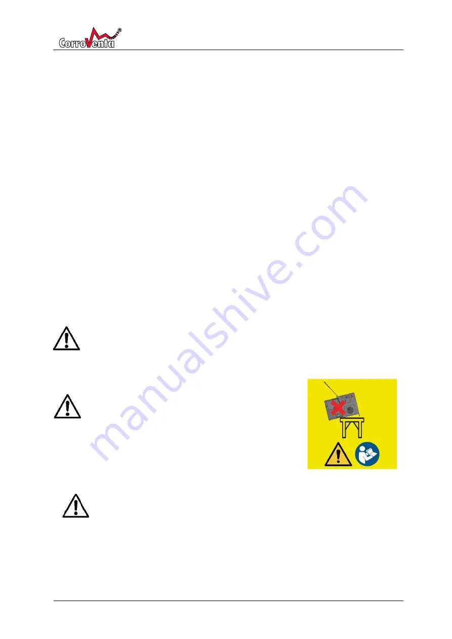
The rotor cassette must not be extracted when the 
machine is in elevated position, such as on a lift table. 
The rotor cassette is provided with a support to prevent 
the machine from falling over and this feature will not 
help prevent accidents if the machine is raised from the 
floor.  


While cleaning the machine, as dust and particles collected from the air flows are 
likely to be present, use appropriate protective equipment. 


The machine exterior is cleaned with a moist cloth. For the interior, use a vacuum cleaner with a 
brush head to remove dust and particles. Carefully and still with the brushed head to prevent 
damage to surface, the rotor is from both sides.  

Summary of Contents for A15ES

Page 1: ...A15ES Corroventa Avfuktning AB 2021 11 1 67 USER MANUAL ADSORPTION DEHUMIDIFIER A15ES ...

Page 2: ...pe 11 How the dehumidifier works 12 Transport and lift 13 Delivery inspection inspection after transport lift 14 Storage 14 Installation 14 Start and stop the machine 16 Emergency stop 17 Adjusting air flow balance 18 Filter monitoring 21 Control panel menu and functions 23 Control Modes and Hysteresis 34 Alarms 35 To network machines 38 Service Reminder 38 Service and Maintenance 39 Filter replac...

Page 3: ...A15ES Corroventa Avfuktning AB 2021 11 3 67 ...

Page 4: ...e control panel the user can adjust and optimize the operation of the A15ES to the work to be undertaken controlling the operation of the fan and selection of proper control mode using either the built in or an external RHT sensor The A15 ES is also compatible with the SuperVision and can thus be remotely operated and controlled through use of smart phone PC or tablet The SuperVision collects and ...

Page 5: ...s the responsibility of the buyer to inspect the product at time of delivery and before use to ensure its good function The product warranty does not cover damage resulting from use of faulty products Changes or modifications to the equipment must not be made without written consent by Corroventa Avfuktning AB The product technical data and or installation and operation instructions can be changed...

Page 6: ...ble or explosive gases can be present neither in the ambient air nor in the air flows through the machine 9 Do not stick objects into the air outlets or intakes as this can cause damage to the machinery as well as human injury 10 Install the dehumidifier steadily and leveled so that it cannot fall over 11 Keep children animals and spectators away from the workplace while installation is undertaken...

Page 7: ... in position The service hatch the filter hatches as well as the electronics cabinet shall be closed and locked 27 For transport and lift the machine must be appropriately secured and the risk area evacuated and continuously monitored 28 If after transport and or lift there is reason to believe the machine may have been damaged it must not be powered and used until it has been inspected by qualifi...

Page 8: ...eneration air Filter hatch process air Lock service hatch Process air inlet Regeneration air inlet Wet air outlet Connections for future expansion modules Regeneration fan Process fläkt Electronics cabinet with control panel Regeneration heater Rotor Rotor motor ...

Page 9: ...cassette may slide out and shift the centre of gravity which could cause the machine to fall over Inside the machine on the rotor cassette and clearly visible when the service hatch is open the below warning label is found The intent of this label is to inform and remind the user that the rotor cassette must never be extracted whilst the machine is in elevated positions an example of which is a li...

Page 10: ...warning symbol intended to remind the user of the above warning in case lighting conditions or other circumstances blocks it from view or if it has been forgotten In addition to the warning labels inlets and outlets as well as filter hatches are marked with their respective functions so as to simplify installation and prevent mistakes ...

Page 11: ...ge of a lower ambient temperature dependency Adsorption functions even well below the freezing point while the capacity of a condensation dehumidifier inevitably decreases rapidly with falling temperature something that is depicted in the diagram below to the left As a rule of thumb a general aid in the selection of type it can be said that adsorption is the primary choice for drying of unheated s...

Page 12: ...h the process fan and is pushed out through the dry air outlet ready to be distributed to where it is needed In parallel with the drying process to prevent the rotor from being saturated at which point the dehumidification would have stopped the rotor is continuously regenerated through use of a completely separated air flow that functions as follows Regeneration air is drawn into the machine thro...

Page 13: ...he service hatch the filter hatches and the electronics cabinet hatch are all closed and locked The below label intended to remind the user of this is found at the bottom of the service hatch The forks of the lifting equipment e g forklift pallet lifter are long big enough for the entire machine to rest securely on them That the machine is secured in the manor appropriate to its weight and to the ...

Page 14: ...ps decreasing the capacities of the respective fans and thus also the dehumidification capacity and energy efficiency As a guideline to the installation planning observe the following Plan the installation and position the machine in such a way that the required ducting is as short as possible Use the same and as big dimensions as possible of hoses pipes for regeneration air and wet air and respec...

Page 15: ...of the machine hatch is preferably of the same height as that of the floor on which the machine is positioned The reason is that the extractable rotor cassette is provided a support to prevent the machine from falling over due to the shifted centre of gravity An elevated position of the machine will prevent the support from reaching the floor and thus the support will no longer prevent accidents I...

Page 16: ...s provided in chapter Filter monitoring Start and stop the machine The machine is equipped with a mains power switch positioned in the lower left corner of the electronics cabinet hatch To start the machine 1 Turn the mains power switch clockwise to position 1 2 Await the control panel start up 3 Once the default view is presented on the control panel there are two alternatives presented Start to ...

Page 17: ...e completed 3 The machine is now in standby For complete shut down proceed by turning mains power switch anti clockwise to position 0 Emergency stop The emergency stop button is positioned next to the mains power switch on the electronics cabinet hatch and it is engaged by a push To reset the emergency stop first turn the emergency stop anti clockwise and then push the reset button located to the ...

Page 18: ... can be increased while still maintaining proper and correct pressure balance between the air flows Before adjustment is undertaken ensure that the machine has been allowed to operate with intended capacity mode for at least 10 minutes preferably more so that it has warmed up and the power consumption of the machine has stabilized The regeneration heaters of the machine are of PTC type which means...

Page 19: ...buttons The minus button lowering the speed of the fan will move the current actual to the left while increasing the speed will move it to the right Make small incremental adjustments wait for the machine to stabilize and then re evaluate Whenever the machine detects rapid and big changes it will present the text Stabilizing please wait The power developed by the PTC heaters is as previously descr...

Page 20: ...ios reflecting a machine with limited ducting 2 When capacity mode is changed the adjustment will have to be repeated If the machine has temporarily been put in standby select Resume to start it again with previous settings and adjustment The other option Start makes the machine forget previous settings including adjustment and brings operation in MAX mode with continuous dehumidification control ...

Page 21: ...unction of the air flow has the appearance depicted below The pressure drop over the increasingly more dirty filter will increase more rapidly with an increase of the air flow as seen by the increasingly steep slope of the curve To get the alarms to trigger at the correct point in time with given installation will thus often require the pressure drop settings to be changed Installations with long ...

Page 22: ...e The difference is that that the last row max pressure presents the pressure level that if exceeded at given current actual fan speed will trigger the alarm A quick comparison of this value 240 Pa in the example and the current actual pressure drop of 180 Pa will give an indication of the filter status Push of Change in the above screen will at first present the user with the possibility of switc...

Page 23: ...nctions are always presented in text and the bottom of the screen At the top level menus the left of these buttons is named Home and a push on this button will immediately lead back to the default view In many of the views there is an Info button which presents information that may be of use to the inexperienced user If the backlight of the display has timed out the first button push serves only t...

Page 24: ...d by another machine Alarm Machine has detected an error Drying indicator Moving when drying is on going Fan indicator Moving when fan is running Fan mode Cont continuous fan If not displayed fan only operates when drying is required INT intermittent fan operation 5 minutes of every hour Read further important information in the following chapter Control mode Indicates how the drying is controlled...

Page 25: ...p for a given task Start Starts the machine with default settings continuous operation with maximum capacity Previous settings made such as the use of sensor control Timer etc If last time it was used the user never pushed stop before the power was cut the machine will automatically resume operation when the countdown has reached zero A push of Pause button will stop the countdown and the machine ...

Page 26: ... operate only when required as determined by the ambient climate The selected control mode is displayed in the lower left corner of the default view The Control Mode selection screen is reached by one push of the upper right button The following basic control modes are available MAN Manual continuous drying RH Drying down to selectable Relative humidity MIX Drying down to selectable mixing ratio g...

Page 27: ... and alternative All is selected rather than one unique sensor e g RHT61 the machine applies worst case and operates as long as any one of the sensors read a humidity above the setpoint When selecting mode other than MAN the machine presents the user with the possibility of determining the setpoint When reaching the setpoint level the drying automatically stops Should the humidity later rise above...

Page 28: ...ature and relative humidity If by these measurements dehumidification is again required the machine will resume dehumidification If on the other hand the measurements give that dehumidification is still not required the fans will stop and the machine will again remain idle for 55 minutes Intermittent fan mode does thus have a potential to save energy in situations where ducting and positioning of ...

Page 29: ...e changed machines equipped with air flow balancing function are preferably re adjusted to ensure optimal performance Note that as described in the chapter on air flow balancing the adjustments are to be made when all ducting is installed and the machine has been allowed time to stabilize Early adjustments will inevitably result in suboptimal performance The A15ES has built in timer functionality ...

Page 30: ...cables before powering up the machines The A15 has networking capabilities allowing it to be remotely monitored and controlled through SuperVision Once established in the network menu the presentation will toggle between the slave units which are referred to with type for instance A4 and address on the bus for instance 101 To change the settings of a slave unit press Edit and the select the given ...

Page 31: ...the more advanced functions are removed from the menu system Keypad lock Possibility to activate deactivate the key pad lock RH Hysteresis Possibility to adjust the hysteresis settings for RH Control Mode The position of the setpoint in the operation span can be set as well as the hysteresis value Dew point Hysteresis Possibility to adjust the hysteresis settings for Dew point DEW Control Mode The...

Page 32: ...th the regeneration air inlet and the wet air outlet are presented In a separate view is also presented the values provided by the temperature and relative humidity sensor by the process air inlet Counters This screen presents the hour and energy counters At the top the resettable work counters are presented followed by the date at which the counters were reset After the date the number of hours e...

Page 33: ...ied this is also presented as a pop up screen Furthermore as long as the error condition remains in the top right corner of the default view there is a warning symbol The alarms presented need not be erased by the user Instead as soon as the machine detects that the functionality is again in place the alarm will disappear automatically ...

Page 34: ...trolled hysteresis to make the operation of the machine stable and prevent excessive on and off switching The table below presents the default settings of the machine If changes are required these can be made under the Setup and Maintenance menu Control mode Hysteresis Setpoint position RH 4 Bottom Dewpoint 2 C Top Mix 0 5 g kg Bottom The below illustrations describe the different hysteresis setti...

Page 35: ... contact with the external RHT sensor s Please check that the cables are correctly mounted When losing the external sensors the machine automatically reverts to using the built in RHT sensor One or more slaves are not responding This alarm is presented when the machine used as Master on a network has lost connection with one or more of its slave machines If it is presented check all the system cab...

Page 36: ...ration and without apparent or known reason the machine shall be checked by service technician before it is put back in operation The overheat protection is mounted behind rubber grommet in the rotor cassette and is found above the rotor within easy reach when the service hatch is opened Please note that the mains power to the machine must be cut before the machine is opened Heater failure The mac...

Page 37: ...ers have been turned off Process air filter not installed Stop the machine and replace the filter If the alarm appears incorrect check and if necessary adjust the alarm settings available in the Filter settings menu under Setup and maintenance See chapter Filter monitoring Dirty process air filter Stop the machine and replace the filter If the alarm appears incorrect check and if necessary adjust ...

Page 38: ...etwork 5 When the network is created at the top of the screen the presentation will toggle between the different slaves If SuperVision is connected the text SuperVision will be presented at the bottom of the screen although it can take up to a minute before this is shown After having followed the steps above all the slave machines are now controlled by the Master This means that they will all be s...

Page 39: ...schedule approximate equivalent and corresponding operation hours has been added for reference only Every 6 months 4750 hours 1 Inspection of and if required replacement of filters 2 Control of function 3 Zeroing of differential pressure sensors Every 12 months 9500 hours 1 Inspection of and if required replacement of filters 2 Inspection and cleaning of machine interior including rotor 3 Control ...

Page 40: ...t the operation is normal and that there are no alarms presented on the control panel Service and repair work including cleaning For service and repair at all times the power must be disconnected from the machine Stop the machine and let it cool down Proceed by turning off the mains power switch and remove the power cable from the power intake Ensure that no other personnel reconnect power to the ...

Page 41: ...osition using a screw driver The rotor tensioner is visible under the actual rotor between the rotor plates 1 Push down on the inner part of the rotor tensioner 2 Insert a screw driver through the hole in the left rotor plate to lock the rotor tensioner in released position 3 Clean the rotor 4 IMPORTANT Remove the screwdriver to let the tensioner back in intended position as soon as the cleaning i...

Page 42: ...following are consumables and examples of accessories available for the A15ES Article number Name 6000733 Filter process air 1004717 Filter regeneration air 1002749 System cable 0 5 m 1002748 System cable 5 m 1002816 Adapter cable hygrostat 1002817 External RHT sensor ES series ...

Page 43: ...xternal hygrostat is connected and used HYG mode check the setting of the hygrostat If RH DEW or MIX control mode is used check the setpoint highlighted at the center of the display and adjust as required Verify that the water symbol starts moving If the control mode and its settings was not the problem continue by checking the capacity mode presented in the top right corner of the default view Fo...

Page 44: ...A15ES Corroventa Avfuktning AB 2022 05 44 67 The machine is operating on timer and currently in stand by If applicable adjust the set point of the humidistat ...

Page 45: ...450 requires air flow balancing function Duct connections Regeneration and wet air diameter mm 160 Process and dry air diameter mm 250 Air filters Filter class regeneration process ISOePM1 55 F7 ISOePM1 55 F7 Power consumption Regeneration W 9300 Motors W 700 Rated power W 10000 Power connection Intake EC CEE 5P 16A 3N 400V 50hz Cable area power cable minimum mm2 2 5 Dimensions Length width height...

Page 46: ...A15ES Corroventa Avfuktning AB 2022 05 46 67 APPENDIX 1 WIRING DIAGRAM ...

Page 47: ...A15ES Corroventa Avfuktning AB 2022 05 47 67 ...

Page 48: ...A15ES Corroventa Avfuktning AB 2022 05 48 67 ...

Page 49: ...A15ES Corroventa Avfuktning AB 2022 05 49 67 ...

Page 50: ...A15ES Corroventa Avfuktning AB 2022 05 50 67 ...

Page 51: ...A15ES Corroventa Avfuktning AB 2022 05 51 67 ...

Page 52: ...A15ES Corroventa Avfuktning AB 2022 05 52 67 ...

Page 53: ...A15ES Corroventa Avfuktning AB 2022 05 53 67 ...

Page 54: ...A15ES Corroventa Avfuktning AB 2022 05 54 67 ...

Page 55: ...A15ES Corroventa Avfuktning AB 2022 05 55 67 ...

Page 56: ...A15ES Corroventa Avfuktning AB 2022 05 56 67 ...

Page 57: ...A15ES Corroventa Avfuktning AB 2022 05 57 67 ...

Page 58: ...A15ES Corroventa Avfuktning AB 2022 05 58 67 ...

Page 59: ...A15ES Corroventa Avfuktning AB 2022 05 59 67 ...

Page 60: ...A15ES Corroventa Avfuktning AB 2022 05 60 67 ...

Page 61: ...A15ES Corroventa Avfuktning AB 2022 05 61 67 ...

Page 62: ...A15ES Corroventa Avfuktning AB 2022 05 62 67 ...

Page 63: ...A15ES Corroventa Avfuktning AB 2022 05 63 67 ...

Page 64: ...A15ES Corroventa Avfuktning AB 2022 05 64 67 ...

Page 65: ...A15ES Corroventa Avfuktning AB 2022 05 65 67 ...

Page 66: ...A15ES Corroventa Avfuktning AB 2022 05 66 67 ...

Page 67: ...A15ES Corroventa Avfuktning AB 2022 05 67 67 ...

Reviews: