CORNING SCF-6 Manual Download Page 3

SRP 003-485 • Issue 6 • October 2006

Page 3

SCF-6 Canister and Inline Splice Closures

KPA-0498

KPA-0499

Admonishments

The precautionary terms used by Corning Cable Systems in its standard recommended
procedures conform to the guidelines expressed in the American National Standards Institute
document (ANSI Z235) for hazard alert messages. Alerts are included in this instruction based
on the following:


DANGER

 indicates an imminently hazardous situation which, if not

avoided, will result in death or serious injury.


WARNING 

indicates a potentially hazardous situation which, if not

avoided, could result in death or serious injury.

  CAUTION

 indicates a hazardous situation which, if not avoided, may

result in minor or moderate injury.

1.

PRODUCT INFORMATION

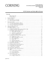
The Corning Cable Systems SCF splice closures are available in both canister and inline
versions (Figure 1). The closures have the capacity for multiple cable ports in addition to two
express cables. The internal fiber management system is designed for splicing fibers and uncut
fiber slack storage.

SCF-6C

SCF-6T

Figure 1 — Splice Closures

Summary of Contents for SCF-6

Page 1: ...Strain relief bracket s 12 5 3 2 Nonmetallic strength member 13 5 3 3 Metallic strength members 13 5 3 4 Large strength members 14 5 4 Install Cable into the End Cap Express Ports 15 5 4 1 Prepare th...

Page 2: ...nd 6T40 EVO 35 EN Product Specifications for Medium Single fiber Splice Closure SCF 6C28 EVO 58 EN Product Specifications for Medium Single fiber Splice Closure SCF 6C22 SRP 000 208 Instruction Large...

Page 3: ...ituation which if not avoided will result in death or serious injury WARNING indicates a potentially hazardous situation which if not avoided could result in death or serious injury CAUTION indicates...

Page 4: ...lts 2 Sealing rings 1 Frame assembly 1 Slack basket none in 02 configurations 1 Accessory kit p n SCF 6T30 ACCY provided with SCF 6T30 and p n SCF 6T40 ACCY provided with SCF 6T40 2 Drop cable strain...

Page 5: ...hers 2 M6x40 Hex screws 2 M6x90 Hex screws 1 Drop port cable strain relief kit p n SCF KT 6CBL containing 2 Drop brackets 2 7 16 x 1 inch hose clamps 2 Central member restraint caps 6 8 washers 4 Nylo...

Page 6: ...nt caps 8 Flat washers 4 M6x40 Hex screws 4 M6x90 Hex screws 1 Cover gasket 1 Drop port cable strain relief kit p n SCF KT 6CBL containing 2 Drop brackets 2 7 16 x 1 inch hose clamps 2 Central member...

Page 7: ...asket 8 Flat washers 4 M6x40 Hex screws 4 M6x90 Hex screws 1 Drop port cable strain relief kit p n SCF KT 6CBL containing 2 Drop brackets 2 7 16 x 1 inch hose clamps 2 Central member restraint caps 6...

Page 8: ...driver 7 16 inch nut driver 10 mm socket and ratchet Flat tip screwdriver Phillips head screwdriver Permanent marker pen Paint marker pen Vinyl tape Hand pump Air pressure gauge Torque wrench Soapy w...

Page 9: ...voltages from lightning causing electrical shock resulting in severe injury or death CAUTION The wearing of safety glasses to protect the eyes from accidental injury is strongly recommended when hand...

Page 10: ...ral Member 15 cm 6 in Bare fibers Bare fibers Buffer tubes Buffer tubes 56 cm 22 in 75 cm 30 in 198 cm 78 in 251 cm 99 in SCF 6T40 SCF 6T30 First End Cap Attached to Frame Assembly Opposite End Cap At...

Page 11: ...1 inch To do this score the armor with a cable knife being careful not to damage the inner sheath if present and split the sheath by flexing it Step 2 Position the grounding clamp base plate under th...

Page 12: ...d ground them Refer to Section 5 2 5 3 1 Strain relief bracket s Install strain relief bracket s onto the opposite side 180 degrees from the grounding clamp when applicable Step 1 Place a hose clamp o...

Page 13: ...etallic strength member behind the bracket install a nut on the restraint cap threaded stud Figure 6 Step 4 Confirm buffer tubes are clear of the strength elements Tighten nut securely Step 5 Repeat f...

Page 14: ...ap 5 3 4 Large strength members For cables with large strength members use the large central member strian relief kit p n SCF MBR CMS purchased separately instead of the restraint caps Figure 9 Step 1...

Page 15: ...lize the end cap while installing and routing fiber is included with the inline closure only Figure 11 The table bracket p n SCF INST BKT6 can be purchased separately Secure the end cap to the bracket...

Page 16: ...ginning at the mark shown in Figure 13 use wax paper backing from the sealing tape to spread the dichtpaste sealing paste evenly around the cable in the area where the sealing tape will be applied All...

Page 17: ...2 Install dummy plug with the closed end of the plug flush against the outside of the end cap Figure 16 5 4 4 Install cable Step 1 Wrap hose clamps and restraint caps with vinyl tape to prevent the sh...

Page 18: ...ts to close the end cap Figure 18 IMPORTANT While tightening ensure that the feet of the strain relief bracket remain inside the tracks Do not use power tools to tighten Step 5 Tighten the bolts until...

Page 19: ...of UCN lubricant to the threads of the vented grounding screw Step 2 Install the vented grounding screw in the threaded insert on the inside of the end cap finger tight plus one half turn approximate...

Page 20: ...mpression Screw Sealing Grommet Toothed Washer KPA 0468 5 7 Install Drop Port Cable into End Cap Step 1 Secure the sealing grommet and toothed washer with the lock nut on the inside of the end cap Ste...

Page 21: ...the cable to the side of the bracket opposite the threaded stud Step 2 Place a hose clamp over the cable and bracket 18 mm 0 75 inch below the sheath end IMPORTANT If grounding hardware is used make...

Page 22: ...p cables Refer to SRP 206 286 Mechanical End Cap Canister Closure Sealing Checklist to ensure all critical steps in Section 5 11 for sealing the closure have been performed accurately Figure 28 Instal...

Page 23: ...Clean fibers according to cable manufacturer s instructions Step 7 Secure the buffer tube to the tray per instructions provided with the splice tray Step 8 Prepare any other splice trays the same way...

Page 24: ...ubricant to the mating surfaces of the end cap gasket Insert the bottom part of the sealing gasket clip into the hole in the sealing ring Figure 37 Step 3 Store the end cap gauge between the splice tr...

Page 25: ...e 38 Gasket Profile Step 5 Place the sealing gasket into the end cap channel Make sure the clip is always on top of the sealing gasket Figure 39 IMPORTANT Position the clip on the gasket away from the...

Page 26: ...t is longer than the channel This is a design feature for maximum performance DO NOT CUT THE GASKET Step 4 Retain a small amount of lubricant for use later Cover the gasket with the remaining lubrican...

Page 27: ...Section 5 13 for sealing the closure have been performed accurately Figure 45 Install Clamping Bars KPA 0488 Figure 46 Hammer Clamping Bars Figure 47 Hammer Locks KPA 0489 Step 4 Close the clamping ba...

Page 28: ...Roll the sealing ring over frame Figure 48 and down to the end cap with arrows as shown IMPORTANT The sealing ring must be installed in the orientation shown KPA 0490 Figure 48 Sealing Ring L U B B R...

Page 29: ...ard the outside of the closure Ensure that both the sealing ring and the canister flange are within the clamping ring Figure 54 NOTE The clamping ring seams must be oriented 90 degrees from the end ca...

Page 30: ...osure for signs of leakage bubbling of soap A correctly sealed closure maintains pressure with no leaks KPA 0295 Figure 56 Valve Stem Figure 57 Pressurize Closure KPA 0297 KPA 0289 Figure 58 Ground Sc...

Page 31: ...1 KPA 0494 Step 3 Perform any tests modifications or examinations of the closure that are necessary Step 4 Reinstall the clamping bars per Section 5 12 3 Step 5 Flash test closure per Section 5 14 on...

Page 32: ...tion 5 16 for inline closures or Section 5 17 for canister closures Step 2 Separate the frame from the end caps by removing the two screws Step 3 Remove the end cap sealing ring Step 4 Remove the two...

Reviews: