Technical Support Manual – 03/2017 Rel. 0
Page 11
6
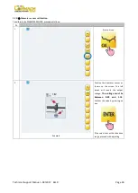
Example
Press on icon to exit the SIGNAL
TEST program.
The values of the displayed signals are expressed in an internal number format and not in any international unit of measure.
The attenuation circuit controls the pick-up signals to avoid saturating the input stage of the CPU-LCD board which offers poor results.
If both pick-up signals differ significantly from the values provided in table T8.2 but are similar to each other, check whether:
•
The adjustment springs are pre-loaded correctly;
•
Both pick-ups are the original ones;
•
The CPU-LCD is operating correctly (it is possible to run this check through the VFC TEST described below).
If both pick-up signals differ significantly from the values provided in table T8.2 and differ from each other, check whether:
•
The pick-up A and pick-up B cables have been connected to the wrong connectors;
•
The pick-up adjustment springs are pre-loaded correctly;
•
The CPU-LCD is operating correctly (it is possible to run this check through the VFC TEST described below).
If only one pick-up signal differs significantly from the values provided in table T11.2, check whether:
•
The pick-up A and pick-up B cables have been connected to the wrong connectors;
•
The pick-up adjustment springs are pre-loaded correctly;
•
Both pick-ups are the original ones;
•
The CPU-LCD is operating correctly (it is possible to run this check through the VFC TEST described below).
Summary of Contents for TOUCH MEC 1000 SONAR
Page 1: ...WHEEL BALANCERS TOUCH MEC 1000 SONAR TECHNICAL SUPPORT MANUAL UK...
Page 2: ......
Page 53: ......


