background image

Product

Support Guide

water

witch

Electronic Water Leveller

17

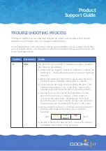
TROUBLESHOOTING PROCESS

The Water Witch is an accurate and reliable electronic auto leveller which should 

provide you with many years of consistent performance.

If your Water Witch is not operating correctly upon installation or you suspect a fault after 

years of reliable service, you will need to consider the problem being experienced and refer 

to the fault table below:

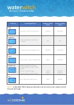
Fault No.

Description

Details

1

FILL

The fill timer has exceeded its maximum run time.  Consider 

the following possibilities:
•  Debris may be caught in sensor so it doesn’t recognise full 

water level – check and clean sensor to ensure it operates 

correctly.

•  Sensor has failed and does not recognise full water level – 

check the sensor operation and replace if required.

•  Solenoid valve has failed and is not filling the pool.  This 

will be recognisable by a low water level.  Replace the 

solenoid valve and check the unit is operating correctly.

•  Volume is set too low and fill timer exceeds run time 

before full water level is attained – check volume is 

correct for the water body.  Alternatively, if this fault 

occurred because a large volume of water was removed 

from the pool, use the Manual Fill feature in the future.

•  Sensor wiring is incorrect – check sensor plug is inserted 

correctly and wiring to the three pins is as per the 

following:

•  Air-lock in the sensor balance line – check water level in 

the balance line relative to the pool level.

GREEN 

BLACK

RED 

YELLOW

LEFT

RIGHT

Summary of Contents for WATER WITCH SMART SENSE

Page 1: ...WATER WITCH SMART SENSE PRODUCT SUPPORT GUIDE waterwitch Electronic Water Leveller...

Page 2: ...ototypes were tested in my shed at home until we were comfortable we had developed the highest quality leveller Many years of industry experience and talking to pool builders about what features they...

Page 3: ...Page 05 Sensor installation Page 06 Solenoid valve installation Page 08 Alternative installation options Page 10 Pump out from tank or trough Page 12 Start up process Page 13 Operating modes Page 15...

Page 4: ...IEC 17067 This Certificate may only be reproduced in its entirety Page 1 of 2 Australian Certification Services Pty Ltd ABN 37 121 022 366 PO Box 627 Jannali NSW 2226 AUSTRALIA Phone 61 2 8521 0726 E...

Page 5: ...lude sufficient overflow provisions to ensure a flooding event does not occur Indoor pools and enclosed projects must also feature sufficient overflow provisions to avoid a potential flooding event Co...

Page 6: ...itable CONTROL BOX WS345 Water Witch Control Box SENSOR WS355 Water Witch Sensor Only 5m WS356 Water Witch Sensor Only 20m WS357 Water Witch Sensor Only 30m WS358 Water Witch Sensor Only 40m WS359 Wat...

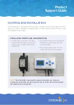
Page 7: ...t 1 2m above ground level and ensure a consistent power source is within reach of the power lead Secure the control box to the desired position on a wall or post with the screws provided Secure the po...

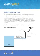
Page 8: ...hed to the top of the Sensor As the ball intersects the light beam at the top of the Sensor the Control Box recognises the full water level Instead of stopping the flow immediately the TIME DELAY adds...

Page 9: ...elbowed up within the equipment area THIS PIPE MUST BE LEVEL TO AVOID AIR LOCKS which will affect flow and performance A 50mm cap is provided to cover the sensor pipe housing and protect the Sensor fr...

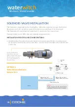
Page 10: ...l Backflow Prevention Valve and Solenoid into water supply fill line ensuring arrows are pointed in the direction of the water flow Connect Solenoid Cable to the Solenoid and Control Box Balance line...

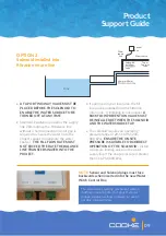
Page 11: ...EVENTION VALVE MUST BE INSTALLED BETWEEN THE SOLENOID AND THE WATER SOURCE TAP The solenoid requires an operating pressure range of 29 116 PSI 200 800 kPa ENSURE THE ONSITE PRESSURE IS SUITABLE FOR CO...

Page 12: ...opriately sized conduit to ensure the Sensor can be accessed for serviceability and replaced if required Small debris capable of affecting sensor performance can build up inside balance tanks It is ad...

Page 13: ...l in the trough may increase dramatically during a significant rainfall event or heavy bather load The trough capacity above the minimum water level must sufficiently allow for this increase INSTALLAT...

Page 14: ...CESS Sensor recognises when the water level increases to the preset maximum height Control Box activates relay switch Power passes through relay switch and activates pump Pump continues to operate unt...

Page 15: ...r supply to Water Witch Press MODE until you reach the SET LEVEL function Confirm Sensor height is correct by checking the SCAN FILL operation when lifting the Sensor up and down Press ENTER to confir...

Page 16: ...pools and large projects 100 000 L 5 000 000 L Other Water features ponds or holding tanks 1 000 L 100 000 L Balance Tank Balance tanks and infinity edge troughs attached to pools or water features C...

Page 17: ...n to operate correctly Take care to correctly estimate the required fill time and ensure the sensor is free of debris to prevent potential water damage onsite OPERATING MODES The Water Witch Smart Sen...

Page 18: ...s or to scroll through the daily runtime for each of the past 14 days The current 24 hour period is displayed as TODAY 00 and each 24 hour period prior to that is recorded as TODAY 01 TODAY 02 etc in...

Page 19: ...t operates correctly Sensor has failed and does not recognise full water level check the sensor operation and replace if required Solenoid valve has failed and is not filling the pool This will be rec...

Page 20: ...dustries if the issue persists 6 OUTPUT A short circuit is detected at the solenoid valve connection replace the solenoid valve 7 UNKNOWN This is typically a program or memory fault reset the unit s p...

Page 21: ...n Gallons 3 SENS TIME 0 3 SEC Sensor reaction time is 3 Sec 1 6 SEC Sensor reaction time is 6 Sec 2 9 SEC Sensor reaction time is 9 Sec 3 12 SEC Sensor reaction time is 12 Sec ADJUST UNIT PARAMETERS H...

Page 22: ...the Control Box as required Annually Remove the solenoid pre filter to clear any debris or contaminant Maintenance checks should be conducted more regularly for commercial applications Product Water...

Page 23: ...or site conditions which may impede or obstruct the correct functioning of the unit Warranty claims are to be lodged at www cookeindustries com au warranty Please note the user must submit the serial...

Page 24: ...waterwitch Electronic Water Leveller Cooke Industries P 1300 652 076 E info cookeindustries com au cookeindustries com au...

Reviews: