Product
Support Guide
water
witch
Electronic Water Leveller
08
SOLENOID VALVE INSTALLATION
The Solenoid is regulated by the Control Box. When the water level is low the Control
Box sends a 24V AC current to open the Solenoid so water flows in to the project.
The Solenoid will close when the water level is restored to the correct level.
Solenoid cables up to 100m long are available by special order.
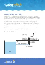
INSTALLATION PROCESS AND CONSIDERATIONS:
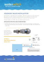
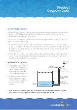
• Install Backflow Prevention Valve and Solenoid into water supply/fill line, ensuring arrows
are pointed in the direction of the water flow. Connect Solenoid Cable to the Solenoid and
Control Box.
Balance line to be
300mm below water level
50mm balance line
POOL
Solenoid &
backflow
valve
Tap or
Two-way
valve
20mm
supply
line
20mm air gap
Water source
Control
Box
Balance line to extend
300mm above water level
NOTE
20mm air gap may not be required where
Ensure the Backflow
Prevention Valve and
Solenoid Valve directional
flow arrows are pointed
in the same direction as
the water flow.
OPTION 1
Solenoid installed into
balance line


