


Arrangement 10
a. Mark the position on the shaft of both bearing races,
setscrews, and the wheel and pulley. Mark the location
and orientation of the inlet cone. Note the clearance
between the wheel and inlet cone.
b. Remove the fan pulley.
c. Remove the inlet cone.
d. Remove the wheel from the shaft. A 2-jaw puller may
be needed.
e. Remove bearing hold-down bolts. Remove shaft and
bearings as one unit.
f. Remove the anti-corrosion coating from the shaft with
a suitable solvent.
g. Remove the bearing from the shaft using a bearing
puller. If a bearing puller is not available, tap on the
bearing with a wood block and hammer to remove it.
h. Smooth and clean the shaft and bearing bore thor-
oughly.
i. Place the bearings into position making sure they are
not on a worn section of the shaft. Tapping the inner
ring face with a soft driver may be required.
Do not
hammer on the housing.
j. The outer ring of the bearing is spherical and swivels
in the housing to compensate for misalignment.
Secure hold-down bolts, but
do not fully tighten
.
k. Align the setscrews on the bearings and tighten one
setscrew on each bearing.
l. Rotate the shaft to allow the bearing outer rings to
fi
nd their center of free movement.
m. Install the wheel on the shaft. Install the inlet cone in
its original location. And adjust bearing position and
inlet cone to center the wheel in the inlet cone.
n. Tighten hold-down bolts to proper torque.
o. Turn the shaft by hand. Resistance should be the
same as it was before hold-down bolts were fully tight-
ened.
p. Tighten bearing setscrews to speci
fi
ed torque. Refer
to Torque chart.
q. Re-install the pulley and adjust the belt tension.
r. Test run and retighten all setscrews and bolts; trim bal-
ance as necessary (.0785 in/sec max.).
After 24 hours of operation, retighten the setscrews to
the appropriate torque. This assures full locking of the
inner race to the shaft. Make sure the socket key or
driver is in good condition with no rounded corners.
The key should be fully engaged in the setscrew and
held squarely to prevent rounding out of the setscrew
socket when applying maximum torque.
Changing Shaft Speed
All belt driven fans with motors up to and including 5 HP
(184T max.) are equipped with variable pitch pulleys. To
change the fan speed, perform the following:
a. Loosen setscrew on driver (motor) pulley and remove
key, if equipped.
b. Turn the pulley rim to open or close the groove facing.
If the pulley has multiple grooves, all must be adjusted
to the same width.
c. After adjustment, inspect for proper belt tension.
Speed Reduction
Open the pulley in order that the belt rides deeper in
the groove (smaller pitch diameter).
Speed Increase
Close the pulley in order that the belt rides higher in
the groove (larger pitch diameter). Ensure that the RPM
limits of the fan and the horsepower limits of the motor
are maintained.
Pulley and Belt Replacement
a. Remove pulleys from their respective shafts.
b. Clean the motor and fan shafts.
c. Clean bores of pulleys and coat the bores with heavy
oil.
d. Remove grease, rust, or burrs from the pulleys and
shafts.
e. Remove burrs from shaft by sanding.
f. Place fan pulley on fan shaft and motor pulley on its
shaft. Damage to the pulleys can occur when exces-
sive force is used in placing the pulleys on their
respective shafts.
g. Tighten in place.
h. Install belts on pulleys and align as described in the
Belt and Pulley Installation
section.
Bearing Replacement
The fan bearings are pillow block ball bearings.
An emery cloth or
fi
le may be needed to remove imper-
fections in the shaft left by the setscrews.
Maximum RPM
CP-BK
Maximum RPM
Class
I
120
2527
1 foot
1/4 inch
Figure 3
Wheel Rotation
Test the fan to ensure the rotation of the wheel is the
same as indicated by the arrow marked Rotation.
115 and 230 Single Phase Motors
Fan wheel rotation is set correctly at the factory. Chang-
ing the rotation of this type of motor should only be
attempted by a quali
fi
ed electrician.
208, 230, and 460, 3 Phase Motors
These motors are electrically reversible by switching two
of the supply leads. For this reason, the rotation of the fan
cannot be restricted to one direction at the factory. See Wir-
ing Diagrams above for speci
fi
c information on reversing
wheel direction.
Do not allow the fan to run in the wrong direction. This
will overheat the motor and cause serious damage. For
3-phase motors, if the fan is running in the wrong direc-
tion, check the control switch. It is possible to inter-
change two leads at this location so that the fan is
operating in the correct direction.
Belt and Pulley Installation
Belt tension is determined by the sound the belts make
when the fan is
fi
rst started. Belts will produce a loud squeal
which dissipates after the fan is operating at full capacity. If
the belt tension is too tight or too loose, lost ef
fi
ciency and
possible damage can occur.
Do not change the pulley pitch diameter to change ten-
sion. This will result in a different fan speed than desired.
a. Loosen motor plate adjustment nuts on bolts and move
motor plate in order that the belts can easily slip into
the grooves on the pulleys. Never pry, roll, or force the
belts over the rim of the pulley.
b. Adjust the motor plate until proper tension is reached.
For proper tension a de
fl
ection of approximately 1/4”
per foot of center distance should be obtained by
fi
rmly
pressing the belt. Refer to
Figure 3
.
c. Lock the motor plate adjustment nuts in place.
d. Ensure pulleys are properly aligned. Refer to
Figure 4
.
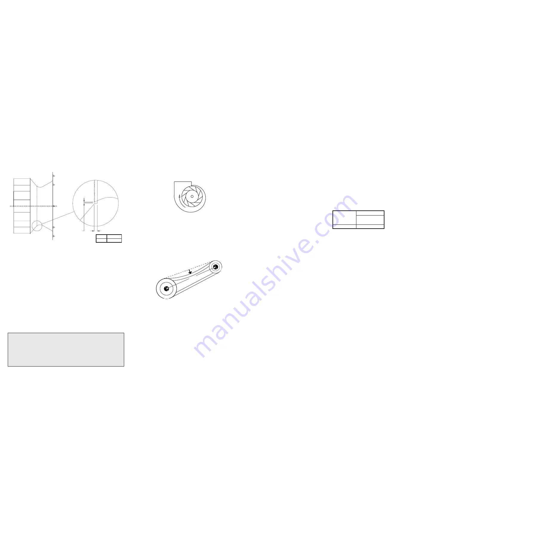
Wheel-to-Inlet Clearance
The correct wheel-to-inlet clearance is critical to proper
fan performance. This clearance should be veri
fi
ed before
initial start-up since rough handling during shipment could
cause a shift in fan components. Refer to wheel/inlet draw-
ing for correct overlap.
Adjust the overlap by loosening the wheel hub and mov-
ing the wheel along the shaft to obtain the correct value.
A uniform radial gap (space between the edge of the
cone and the edge of the inlet) is obtained by loosening the
inlet cone bolts and repositioning the inlet cone.
Wiring Installation
All wiring should be in accordance with local ordinances
and the National Electrical Code, NFPA 70. Ensure the
power supply (voltage, frequency, and current carrying
capacity of wires) is in accordance with the motor name-
plate.
Lock off all power sources before unit is wired to power
source.
Leave enough slack in the wiring to allow for motor move-
ment when adjusting belt tension. Some fractional motors
have to be removed in order to make the connection with
the terminal box at the end of the motor. To remove motor,
remove bolts securing motor base to power assembly. Do
not remove motor mounting bolts.
Units with Arrangement 10 have a hole provided at the
base of the bearing pedestal to accommodate wiring.
Follow the wiring diagram for the disconnect switch
(Pages 4 & 5) and the wiring diagram provided with the
motor. Correctly label the circuit on the main power box
and always identify a closed switch to promote safety
(i.e., red tape over a closed switch).
WHEEL/INLET
WHEEL/INLET
OVERLAP
VERLAP
RADIAL
RADIAL
CLEARANCE
CLEARANCE
OVERLAP
VERLAP
Personal Safety
Disconnect switches are recommended. Place
the disconnect switch near the fan in order that the
power can be swiftly cut off in case of an emergency,
and in order that maintenance personnel are provided
complete control of the power source.
7
2
Backward Inclined
Size Overlap
120
5/8”


