


50
SM-Universal Encoder Plus User Guide
www.controltechniques.com
Issue Number: 6
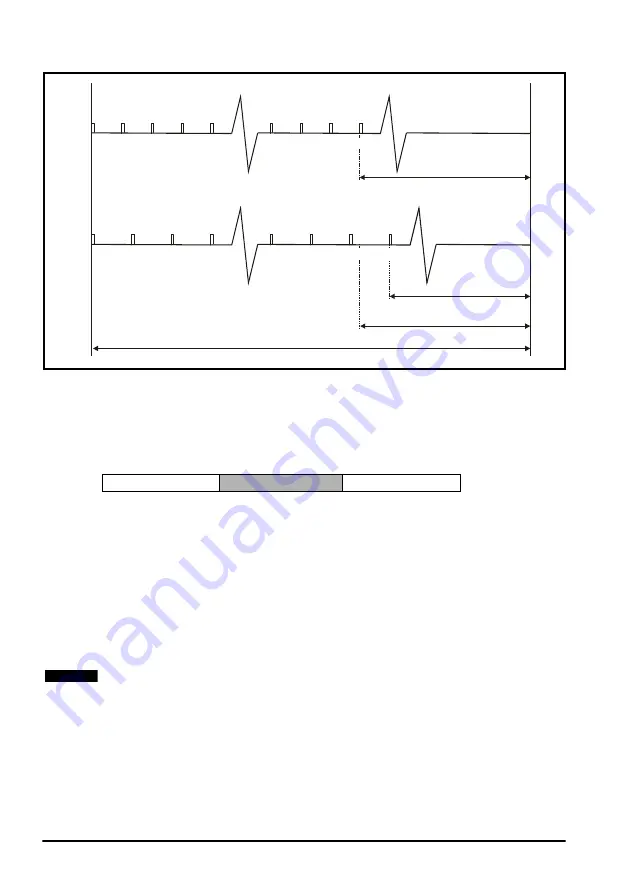
Figure 6-2 SSI data transfer at maximum resolution and 300 / 400 kHz clock
frequency
A typical 32-bit source parameter example is given below:
The master controls the number of bits transferred and how many of the bits are the
turn’s information. For example a 32-bit parameter could contain 8 bits of turn
information as the most significant part, and 10 bits of positional information as the next
significant part. The bit string is shown below:
The master is set to transfer 18 bits (plus one for the start/latch). The least significant bit
sent will be forced low to indicate that the power supply is fine. The master is also set to
take the most significant 8 bits as the turns information. The user is responsible for
preparing the source parameter.
Output initialisation
During power-up the source position may not be valid. The simulator will wait until the
position feedback source has been initialised before using the current position as the
first output position. As a result the SSI output will be held high until the source has
been initialised which will trigger the master to trip on power supply failure. Once
initialised the simulator will not stop even if the source device is re-initialised or trips.
400kHz
Clock
300kHz
Clock
2.5 s
µ
5 s
µ
7.5 s
µ
10 s
µ
3.3 s
µ
6.6 s
µ
9.9 s
µ
5 s
µ
7.5 s
µ
10 s
µ
115 s
µ
120 s
µ
117.5 s
µ
156.6 s
µ
Bit 0
Bit 1
Bit 2
Bit 3
Bit 46
Bit 47
Bit 48
Bit 0
Bit 1
Bit 2
Bit 46
Bit 47
Bit 48
153.3 s
µ
127.5 s
µ
250 s
µ
86.7 s
µ
122.5 s
µ
163.3 s
µ
Minimum of 90 s pause
required for reliable operation
µ
1 drive sample period
160 s
µ
0
31 24 23 14 13 0
Turns information
Position
Do not care
If the source is not feedback device, the simulator waits until all feedback device
sources have initialise before the starting to output. The wait for initialisation does not
occur if the drive software version is less than
V01.08.00
NOTE