


EMM-µD3h EMM-µD3h-p EMM-µD3h-485 instruction manual
IM380-U v3.1
pag. 3 / 12
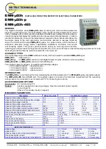
WIRING DIAGRAMS
P1
S1
S1
S2
L1
L2
L3
THREE PHASE LINE WIRING WITH 3 WIRES AND 2 CT
(AARON Wiring)
P1
P2
S2
P2
LOAD
P1
P2
S1
S2
N
L
SINGLE PHASE WIRING
Should the case be that the instrument is used on single
phase, it has to be considered that the valid measures are
related to the phase L1, others realated to the three phase
system are not to be considered.
P1
P1
P1
P2
S1
S1
S1
S2
N
L1
L2
L3
IL2
IL1
IL3
S1
S2
V
L1
V
L2
V
L3
N
m
e
a
s
u
ri
n
g
c
u
rr
e
n
t
in
p
u
ts
m
e
a
su
ri
n
g
v
o
lta
g
e
in
p
u
ts
On three wires line (without neutral or with not
distribuited neutral) DON’T wire the N terminal.
WIRING IN A THREE PHASE LINE WITH 3 OR 4 WIRES
EMM
LOAD
aux1
aux2
aux iliary
supply
V
L1
V
L2
V
L3
N
m
e
a
su
ri
n
g
v
o
lta
g
e
in
p
u
ts
EMM
aux1
aux2
aux iliary
supply
V
L1
V
L2
V
L3
N
m
e
a
su
ri
n
g
v
o
lta
g
e
in
p
u
ts
EMM
aux1
aux2
aux iliary
supply
P1
S1
N
L1
L2
L3
V
L1
V
L2
V
L3
N
m
e
a
su
ri
n
g
v
o
lta
g
e
in
p
u
ts
On three wires line (without neutral or with not
distribuited neutral) DON’T wire the N terminal.
BALANCED THREE PHASE LINE WIRING WITH
3 OR 4 WIRES
EMM
LOAD
aux1
aux2
aux iliary
supply
LOAD
S2
S1
S1
S2
IL2
IL1
IL3
S1
S2
m
e
a
s
u
ri
n
g
c
u
rr
e
n
t
in
p
u
ts
S2
S1
S1
S2
IL2
IL1
IL3
S1
S2
m
e
a
s
u
ri
n
g
c
u
rr
e
n
t
in
p
u
ts
S2
S1
S1
S2
IL2
IL1
IL3
S1
S2
m
e
a
s
u
ri
n
g
c
u
rr
e
n
t
in
p
u
ts
S2
S1
S1
S2
RS485 Connection
EMM
aux1
aux2
aux iliary
supply
RS485
B
A
COM
EMM
aux1
aux2
aux iliary
supply
RS485
B
A
COM
Connection with shielded
Connection with not shielded
Digital Output connection
EMM
aux1
aux2
aux iliary
supply
Co DO1
DO2


