


EMM-µD3h EMM-µD3h-p EMM-µD3h-485 instruction manual
IM380-U v3.1
pag. 2 / 12
INSTALLATION
WARNING FOR THE USER
Read carefully the instructions/indications contained in this manual before installing and using the instrument.
The instrument described in this manual is intended for use by properly trained staff only.
SAFETY
This instrument has been manufactured and tested in compliance with EN 61010-1 (IEC1010) standards. In order to maintain these
conditions and to ensure safe operation, the person must comply with the indications and markings contained in the manual. When
the instrument is received, before beginning installation, check that it's OK and it has not suffered any damage during trans port. When
starting installations make sure that the operating voltage and mains voltages are compatible with the device instructions. The
instrument power supply must not be earthen. Only qualified and authorised personnel must carry out maintenance and/or repair . If
there is ever the suspicious that, that there is a lack of safety, during operation, the instrument must be disconnected and cautions
taken against accidental use.
Operation is no longer safe when: The instrument doesn't work. - There is clearly visible damage. - After serious damage
occurred during transport. - After a storage under unfavourable conditions.
The fixing to the DIN rail is granted by the rear spring fixing device.
It’s better to put an external protection with fuses for the voltage inputs and to use adapted cables for the working currents and
voltages: section from 0.5 to 4 mm
2
.
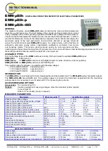
WIRING
For a correct use of the device, the wiring diagram contained in the
present manual must be respected. The connections are available
on the screw terminals:
- Power supply:
The auxiliary power supply is taken from the terminals aux1 and
aux2.
The rated supply voltages can be:
standard:
Vn 230V ± 15% 50-60Hz
under request: Vn 110V ± 15% 50-60Hz
under request Vn 400V ± 15% 50-60Hz
- measuring voltage inputs:
4 terminals are available for wiring to the 3 phase and neutral of the
measuring network, the maximum voltage phase to phase shouldn't
be over 500V rms and 290V between phase and neutral.
In case of a 3-phase system without neutral or non-distributed
neutral, leave terminal N free.
For single phase use, wiring should be done between terminals L1
and N and bridge L2 and L3 phases to neutral N.
- measuring current inputs:
6
terminals are available for wiring to 3 external CT’s with secondary
5A, it’s possible to use 2 CT’s on 3 wires lines with (Aron three-
phase wiring) and the use of 1 CT in case of single phase system
(input IL1). External CT’s must always be used.
Don't connect CT's secondary to the earth.
The instrument’s SETUP menu allows to set the transformation rate
of the external CT and it’s possible to visualise readings of current
up 999 A. Should the case be that calculated current is higher than
the maximum value, the display will show the over range condition.
The maximum setting of the transformation ratio is 2000/5=400
NOTE: For a correct measuring of the power factor and energies and powers it's a must to respect the phase sequence. The
connections between current and voltage phase inputs must not be inverted (for example, CT placed on phase L1 must
correspond to the I1 input). So as it is not correct to invert S
1 and S2 of the CT’s terminals.
V
L
3
V
L
2
V
L
1
N
a
u
x1
a
u
x2
IL
3
IL
2
IL
1
D
o
2
D
o
1
Co
measuring voltage
inputs
max 500 V L-L
auxiliary
supply
110 or 230 or 400Vac
measuring current
inputs
max 5 A
options
S1
S2
S2
S2
S1
S1
c
A
B
RS485 serial port
2 X digital output
max 230Vac/dc 150mA
L1
L2
L3
L
V
L-N
A
kW
kVAr
kVA
V
L-L
...h
Hz /
ou t
SET
P.F.
EMM-µD3
ma x
av g
VL1
VL2
VL3
N
aux2 aux1
volta ge inputs
V aux
S1
S1
S1
S2
S2
S2 Do2
c
Co
B
Do1
A
IL1
IL2
IL3
curr ent inputs


