5. Using the Memory Address Map
ADI16-4(FIT)GY
55
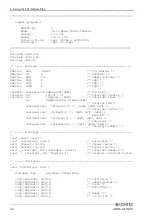
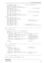
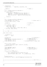
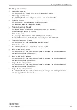
Examples
Flowchart
Following is an example in which the ADI16-4(FIT)GY is installed at Device ID :0:
Figure 5.1. Installed at Device ID:0
No
Yes
Start
End
Set analog input range
Set Module Startup in
module startup register
Get analog input data
Opened successfully?
Closing processing
Open proc
essing
Analog module type?
Show analog input data
Check error status
Yes
No
Error status can be checked by reading address: 300011h.
Determine category by reading address:301000h.
For analog-type module, category is "02h".
Set analog input range.
Analog input range is written to address: 301013h.
Default is "00h" (Analog input range: -10V to +10V).
This value need not be written when the default is used.
Module is started by writing "01h" to address: 301010h.
When started, the module can get valid analog input data.
By reading 2 bytes from address: 304000h,
the module can get analog input data from CH0.
In subsequent operations, the module can get analog
input data with 2 bytes at a time, up to CH3.


