4. Using the I/O Address Map
ADI16-4(FIT)GY
35
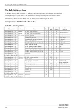
Setting an Interrupt Source
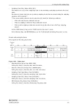
This option allows you to specify an interrupt signal generation source.
The control port that sets an interrupt source assumes the following state:
Starting
I/O
address
D7
D6
D5
D4
D3
D2
D1
D0
Output
Command
+24
(18h)
0
0
0
0
0
0
0
1
D7
D6
D5
D4
D3
D2
D1
D0
Interrupt Mask0
+28
(1Ch)
1
1
Setting
Clock Error
Sampling
Clock Input
1
Data Over
Write Error
1
Data Read
Enable
Interrupt Mask1
+29
(1Dh)
1
1
1
FIFO
Memory
Flag
1
1
1
1
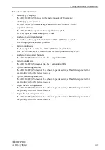
Figure 4.25. Interrupt sources
When the value [1] is output as an interrupt source, the control port is masked; when the value [0] is
output, the port is set as an interrupt source.
[1] Masked
* Initialized state
[0] Interrupt Request Enable
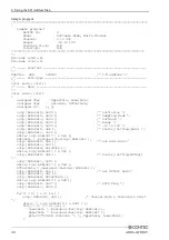
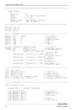
Following are examples in which a timer cycle is set :
outp( ADR+24, 0x1 );
outp( ADR+28, InterruptFactor );

