4. Using the I/O Address Map
32
ADI16-4(FIT)GY
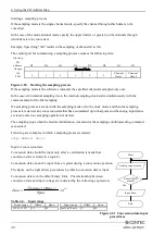
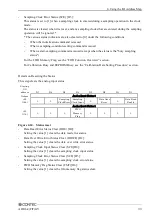
Details on the Analog Input Status
The analog input status shows the status of an A/D conversion operation.
Starting
I/O
address
D7
D6
D5
D4
D3
D2
D1
D0
Input
Analog Input Status 0
+22
(16h)
0
0
Sampling
Clock Error
Sampling
Clock Input
0
Data Over
Error
0
Data Read
Enable
Analog Input Status 1
+23
(17h)
0
0
0
FIFO
Memory
Flag
Calibration
Busy
EEPROM
Busy
0
0
Figure 4.23. Analog input status
-
Data Read Enabled Status (DRE) [D0]:
This indicates that conversion data is available that can be read.
If the channel mode is the single-channel mode, when any readable conversion data is stored, this
status is set to [1]. In the case of the multi-channel mode, this status is set to [1] when conversion
data equal to the number of specified channels is available.
When readable conversion data is depleted, this status is cleared. *
-
Data Overwrite Error Status (DOWE) [D2]:
The status bit is set to 1 when FIFO memory becomes full as the data input interval is longer than
the sampling clock interval during operation in clock mode. If this status is detected, you need to
either increase the sampling clock interval or reduce the READ processing time.
The bit is cleared by a status reset.
-
Sampling Clock Input Status (SCI) [D4]:
This status is set to [1] when a sampling clock is entered after a start-sampling command is issued
in the clock mode. The status is cleared when it is reset. *


