4. Using the I/O Address Map
ADI16-4(FIT)GY
25
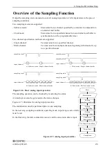
Overview of the Sampling Function
Output the sampling start command to convert analog input data to 16-bit digital data in the pre-set
sampling conditions.
Two sampling modes are supported:
- Software mode:
Stores data from a channel specified by a data-fetch command into
an internal read buffer.
- Clock mode:
Stores data from a specified channel into an internal read buffer in
synchronization with a programmable timer.
Two channel specification methods are supported:
- Single channel:
Can read data from a specified channel.
- Multi-channel:
Can read data from multiple channel, beginning with channel 0, up
to a specified channel.
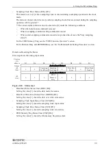
Figure 4.14. Basic analog input operation
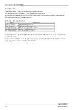
The sampling operation can be checked by monitoring the status.
An interrupt can also be generated as the status changes.
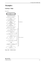
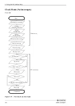
Figure 4.15. illustrates the analog input procedure.
The initialization must be performed prior to any sampling.
In the next step, sampling conditions (operating mode, input range, and so forth)
must be set.
In the final step, the start command is issued, and the conversion data is input.
1ch
1ch
3ch
2ch
1ch
0ch
3ch
2ch
1ch
0ch
sampling start
input channel
3ch
1ch
sampling start
input channel
3ch
2ch
1ch
0ch
3ch
2ch
1ch
0ch
b. Software mode - Multi channel mode
a. Software mode - Single channel mode
sampling start
input channel
sampling clock
sampling clock
sampling start
input channel
c. Clock mode - Single channel mode
d. Clock mode - Multi channel mode
Figure 4.15 Analog input procedure
Start
Initialization
Starting an sapmling
Setting
an input range
Input data
Completion
Setting
the FIFO flag
Calibration
data setting
Setting
sampling conditions

