background image


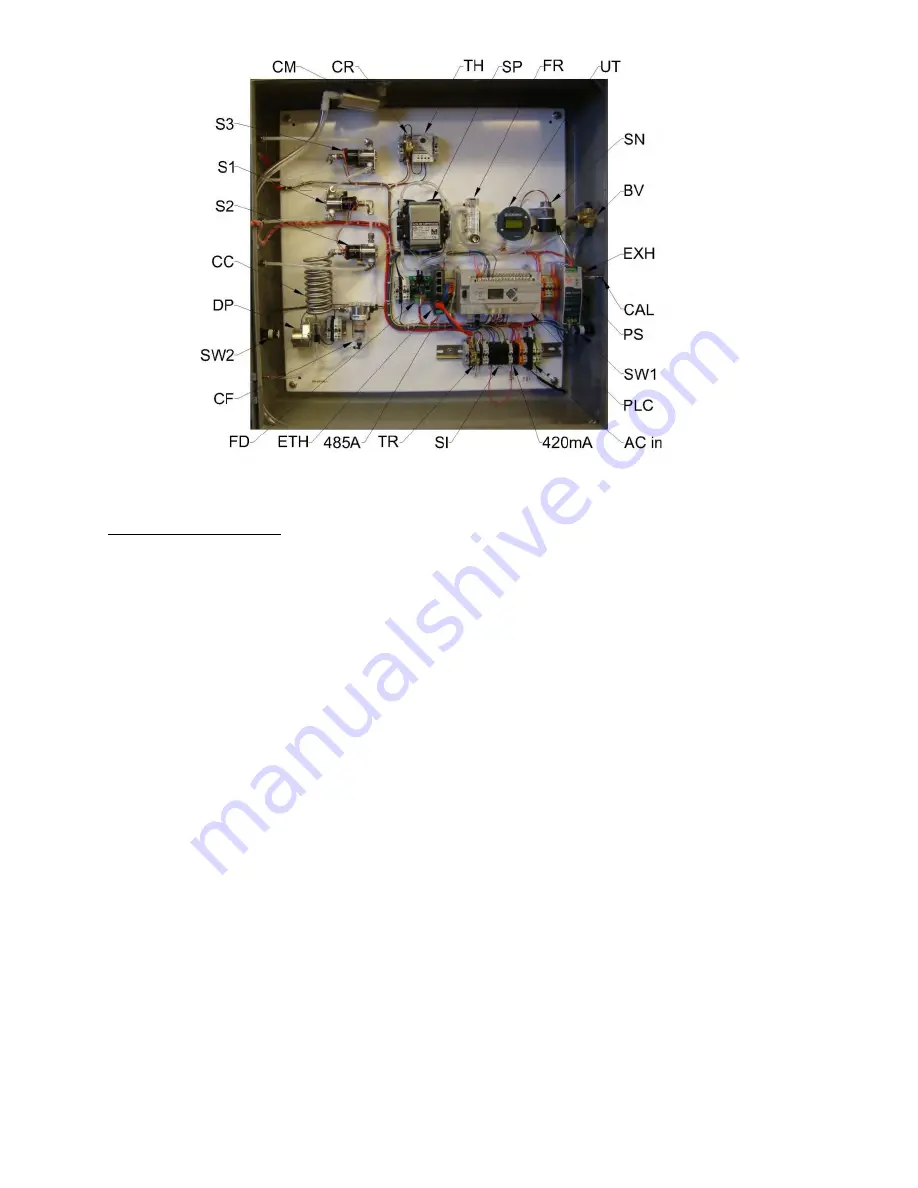
Figure 1:  CS0352-MP Components 

CS0352-MP Components – Labels, Descriptions, and Part Numbers

PLC 
PS 
UT 
SN 
FD 
SP 
SW1 
DP 
SW2 
ETH 
485A 
S1 
S2 
S3 
TH 
TR 
CR 
FR 
CF 
CC 
BV 
CAL 
EXH 
ACin 
SI 
420mA 

Allen Bradley 1400 
Meanwell 24VDC 5A Supply 
500PPM CO Detector Card 
1000PPM CO Sensor 
Flow Detector Card 
120Vac 12 LPM Sample Pump 
Sample Pump Switch 
115Vac Peristaltic Drain Pump 
Drain Pump Switch 
Moxa Ethernet Switch 
RS485 to Serial Adaptor 
Probe Select Solenoid 
Pressure Release Solenoid 
H.P. Blow Back Solenoid 
Thermostat 
Trouble Relay 
Cooler Solenoid Relay 
.4-5.0LPM Flow Regulator 
Coalescing Filter 
Cooling Coil 
3-way Ball Valve (Calibration) 
Calibration Port 
Exhaust Port 
120VAC Supply Input 
System Inputs 
4-20mA CO Level Output 

1766-L32BWA 
SDR-120-24 
900732-03 
P2261-3 
900724 
AL-6SB 
P1907-SL 
SP101R.104 
P1907-SL 
EDS-205 
1763-NC01 
3CBX4S-Y-24VDC 
3CBX4S-Y-24VDC 
3CBX4S-Y-24VDC 
Vortex 747 System 
814-3028 
814-3028 
FL2013 
2383T47 
Non Inventory Item 
46095K41 
DMA3 
DMA3 
N/A 
N/A 
N/A 

Summary of Contents for CS0352-MP

Page 1: ...CONSPEC CONTROLS CS0352 MP User Manual 1 24 2017 Rev 3 ...

Page 2: ...urpose 1 System Overview 1 CS0352 MP Components 2 Panel View Screens 3 Modes 6 Trouble Conditions 7 CO Sensor Calibration 9 Flow Detector Calibration 10 See also 10 Replacement Parts 10 Contact Information 10 ...

Page 3: ...to detect smoldering coal that may have fallen to the bottom of the mill The pump is disabled and sampling ceases during a deluge or spray down of the mill to avoid the system from taking in too much water The PLC determines the mill status by several inputs from the MillPro system and acts accordingly The CS0352 MP performs scheduled high pressure blow backs to clear the sintered metal probes of ...

Page 4: ...Moxa Ethernet Switch RS485 to Serial Adaptor Probe Select Solenoid Pressure Release Solenoid H P Blow Back Solenoid Thermostat Trouble Relay Cooler Solenoid Relay 4 5 0LPM Flow Regulator Coalescing Filter Cooling Coil 3 way Ball Valve Calibration Calibration Port Exhaust Port 120VAC Supply Input System Inputs 4 20mA CO Level Output 1766 L32BWA SDR 120 24 900732 03 P2261 3 900724 AL 6SB P1907 SL SP...

Page 5: ... Cooler Solenoid Vortec Cooler Vortex 747 System 2711C T6T Vortex 747 System Vortex 747 System PanelView Screens Main screen The main screen contains a link to all the other screens All the screens are accessible from the main screen The screens are Maintenance Overview PV Config Alarm Log ...

Page 6: ... information all on one screen for easy viewing The panel status sensor status an approximated 4 20mA value CO value hour long trend window MillPro status Mill Status and logging information are all displayed The logs keep track of operation times so the user can predict when components will need maintenance or replacement The About screen can be accessed from the overview screen The about screen ...

Page 7: ...s such as a blocked probe during start up mode the PLC immediately goes into alarm and energizes the trouble relay This error is displayed on the panel view screen and needs to be cleared or acknowledged A record of alarms and errors is kept in this screen and can be cleared if desired ...

Page 8: ...t Up Mode Start up mode is the first mode that the sample panel goes into upon being enabled Start up mode allows pressure to be created within the lines and give the flow detector time to stabilize The sample panel enters start up mode every time that the pump turns on If there is a low flow condition or the line is clogged during start up mode the sample panel goes into an error condition and th...

Page 9: ...Mode Maintenance Mode should be entered by the user anytime that work is being performed on the system This will ensure that the scheduled blow back to occur every 30 minutes will not happen and the pumps and solenoids will be turned off unless forced on by the user Maintenance Mode is a useful tool for trouble shooting and checking for proper operation of individual components From this mode the ...

Page 10: ...n the user definable time frame Error will clear once panel is put into startup mode Alarm 1 The gas value has exceeded the alarm 1 user definable set point Alarm 2 The gas value has exceeded the alarm 2 user definable set point Temperature error The internal temperature of the panel is outside of the 4F 120F range of the gas sensor Flow Cal Error The pump is off but the flow detector still signal...

Page 11: ...d be applied to the sensor Open the valve on the regulator and apply the zero gas Make sure that the adjustable flow regulator inside the panel is fully open to allow maximum flow Apply the zero gas for two minutes After two minutes or a stabilized reading point the IR programmer at the Universal Transmitter and press enter The status light will now turn red indicating the monitor is ready to have...

Page 12: ...igher or lower low flow set point Once a successful calibration has been accepted lower the flow slowly to make sure the indicator light turns red at approximately 1 1 5 LPM and that you hear the relay energize and click If the calibration worked correctly raise the flow to approximately 3 LPM and close the door and put the panel back into run mode If the light does not turn red within 5 LPM of th...

Reviews: