background image

Operating Instructions 


750 W 27 V pickup 

CQF 04/2 + Interface M12 


BAL9100-0145a-EN 
www.conductix.com 

translated document 

Page 34 of 40 


Status relay closed 

Status relay open 

Error relay open 

Alert relay closed 

See a) or b) 

See c) 

See d) 

Alert relay open 

Normal operation: 
See chapter 10.2 

Normal operation: 
See chapter 10.2 

See e) 

Table 1 Relay outputs and their meaning
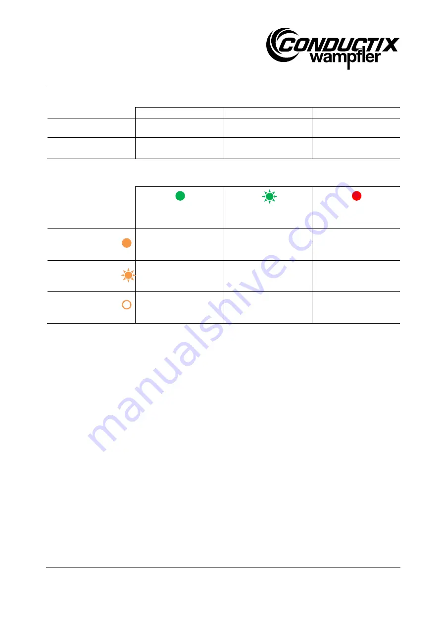


Green LED on 

(Status relay closed) 


Green LED flashes 

(Status relay open) 


Red LED on 
 

Orange LED 
on 

(Alert relay closed) 

See a) 

-- 

-- 

Orange LED  
flashes  

(Alert relay closed) 

See b) 

See c) 

See d) 

Orange LED 
off 

(Alert relay open) 

Normal operation: 
See chapter 10.2 

Normal operation: 
See chapter 10.2 

See e) 

Table 2 LED displays and their meaning 


a)


The maximum available peak power has been exceeded. Set according to the chapters 4.1. 7.5 and 8.3 ensure the 
retrieved performance matches the possible performance. 


b)


The internal device temperature is approaching the maximum. If the average retrieved performance does not exceed the 
specified values according to the sections 4.1, 4.2, 7.5, the alert will have no immediate consequences and operation will 
continue. If, on the other hand, such an alert persists for a long period of time and has never been present before, this can 
be indicative, for example, of severe soiling of the heat sink (note also chapter 11). Without corrective action, this can result 
in a temperature error (see case d). 


c)


Automatic shutdown via the pilot contact function, with disconnected connecting cable. 


d)


The max. permissible internal device temperature has been exceeded. The alert (LED flashing and alert relay closed) 
persists until it falls below a reasonable temperature value. The device itself remains in error status until a reset has 
occurred (see chapter 10.4). Set according to the chapters 4.1. 4.2 and 7.5 ensure the retrieved performance matches the 
possible performance. 


e)


The device has been shut down automatically. More about this in the chapter 4.3. If the cause of the error is detected and 
eliminated, carry out a reset (see chapter 10.4). If the error cannot be attributed to external influences, the device is not 
ready for operation and must be examined by a specialist. Details on the procedure can be found in the chapter 12. 


Summary of Contents for 91212-332-3124850

Page 1: ...ating Instructions 750 W 27 V pickup CQF 04 2 Interface M12 BAL9100 0145a EN www conductix com translated document Page 1 of 40 Order number 91212 332 3124850 F Pickup 750 W 27 V DC CQF 04 2 Controlle...

Page 2: ...symbols 7 2 2 Personnel requirements 8 2 2 1 Qualifications 8 2 2 2 Unauthorized personnel 8 2 3 Advisory information for the user 9 3 Intended use 10 4 Technical data 11 4 1 Electrical data 11 4 2 Am...

Page 3: ...the interface recommended 21 7 4 3 Example Interface not used 22 7 5 Installation location and conditions 23 7 5 1 Position 23 7 5 2 Required air flow 23 7 5 3 Proximity to iron steel ferromagnetic m...

Page 4: ...document are protected by copyright and are the property of their respective companies We reserve the right to make technical changes to the illustrations and specifications in this document in order...

Page 5: ...00 0037 for floor installations and especially the EHB installation instructions must be observed if relevant for installation and operation of the device Design adjustments and commissioning may only...

Page 6: ...ur right to further claims remains unaffected 1 4 Replacement parts WARNING Incorrect replacement parts are a safety hazard Incorrect or faulty replacement parts can impair safety and result in damage...

Page 7: ...avoided may result in death or serious injury CAUTION indicates a possibly hazardous situation which if not avoided may result in moderate or minor injury and property damage NOTE Tips and recommenda...

Page 8: ...assigned to them and the potential dangers arising from improper actions Specialist personnel consists of persons capable of performing assigned tasks and independently identifying and avoiding poten...

Page 9: ...ff according to the safety regulations are persons that are familiar with the installation assembly commissioning and operation of the energy supply system and that have the appropriate qualifications...

Page 10: ...iates from or goes beyond the intended use of the devices can result in hazardous situations The device may only be used as intended Follow all information in these operating instructions strictly The...

Page 11: ...ea of the field around the track cables 4 1 Electrical data Input IPT track 125 A 20 kHz conductor distance 100 mm Output voltage 27 V DC 7 Maximum output current 27 8 A DC Output peak power 750 W 40...

Page 12: ...d mounting spaces Operation For indoor operation only The use in explosion prone areas or in areas where the pickup is exposed to harmful oils acids vapors dust gases radiation humidity etc is explici...

Page 13: ...re Automatic shutdown by internal temperature monitoring e g by exceeding the permissible ambient temperature and or the maximum permissible output power 4 4 Mechanical integration Dimensions See draw...

Page 14: ...p CQF 04 2 Interface M12 BAL9100 0145a EN www conductix com translated document Page 14 of 40 4 5 Electrical connections DC power output CQF 04 2 ILME or comparable Interface DC power output Order con...

Page 15: ...keep the voltage drops on the leads as small as possible The device is connected to the load using all four outputs two positive and two negative The cable lengths of the connecting cables of the sam...

Page 16: ...ge even without connecting cables as long as the primary side of the IP system is active 4 5 4 ESD protection DANGER Risk of electric shock Because IPT is an isolated system depending on the vehicle d...

Page 17: ...ransport damage is externally visible proceed as follows Do not accept delivery or accept it only with reservations Note the scope of damage on the transport documents or on the transporter s delivery...

Page 18: ...of packed parts Store packed parts under the following conditions Do not store outdoors Store in a dry dust free place Do not expose to aggressive media Protect from direct sunlight Avoid mechanical v...

Page 19: ...or material damage Unpack components after they are received or before starting the installation Carefully check the components for any transport or storage damage damaged packaging damage to housings...

Page 20: ...the plug under load see also chapter 4 3 If the pilot contacts in the connector half are bridged on the device side the device cannot detect if the connection cable on the load side is unplugged or i...

Page 21: ...terface are connected recommended The interface makes it possible to power up and shut down the device under load It also allows a simple reset of the device in the event of a detected error or protec...

Page 22: ...91000 400 3089971 The pilot contacts are not intended to serve as on off switches It is therefore not recommended to interrupt pilot connection under load The purpose of the switch shown below between...

Page 23: ...unting with the heat sink pointing downwards is not permitted The devices must be mounted parallel to the primary track and centered over the lines see drawing A nominal distance of 10 mm between the...

Page 24: ...in the vicinity of the device will affect the behavior of the device lower output power higher heat losses etc are possible Observe the corresponding notes in our installation instructions for floor i...

Page 25: ...shock or vibration It is also important to ensure that the convection cooling is not restricted by installation on the vehicle 7 5 5 Additional mechanical protection measure WARNING Risk of burns due...

Page 26: ...4 V supply If the device is in release mode and the status relay is closed contacts 3 and 7 the max permissible current is 150 mA NOTE If the interface is not being used Even if the existing possibili...

Page 27: ...ace to the lower edge of the device and positioning above the primary track horizontally in the middle The following graphs show the typically available output powers over a straight IPT track as func...

Page 28: ...o not rely on the connecting cables alone as the device will not be de energized and without voltage even without connecting cables as long as the primary side of the IP system is active Turn off the...

Page 29: ...ng condition In conjunction with the other relay outputs conclusions can also be drawn about the pilot contact functions see chapter 8 5 Status relay contacts 3 7 Is normally opened It closes when the...

Page 30: ...it the hiccup mode If such situations repeat in particular repeatedly at specific points of the path the load design and or possibly the tracking must be checked there 8 7 Caution during operation DAN...

Page 31: ...ns and property All installation and commissioning as well as maintenance and disassembly has to be carried out by qualified personnel IEC 364 respectively ENELEC HD 384 or DIN VDE 0100 and IEC 664 or...

Page 32: ...5V LED LED green 12V LED The interface M12 contains three potential free relay contacts with a common contact contact 3 More information about the relay contacts can be found in the chapter 8 5 Error...

Page 33: ...Green 12V LED on 12 V supply available Attention in addition a warning can be shown via a closed alert relay and the orange warning LED This does not necessarily mean that the device is being operated...

Page 34: ...to the sections 4 1 4 2 7 5 the alert will have no immediate consequences and operation will continue If on the other hand such an alert persists for a long period of time and has never been present...

Page 35: ...acts that is disconnecting and reinserting the connection cable of the DC power output NOTE The pilot contacts are not intended as on off switches therefore disconnecting them under load should be avo...

Page 36: ...roperly executed repair work Improper repair work can result in serious injury to persons and property Repair work may only be performed by trained personnel or Conductix Wampfler technicians Generall...

Page 37: ...ff according to the safety regulations are persons that are familiar with the installation assembly commissioning and operation of the energy supply system and that have the appropriate qualifications...

Page 38: ...with plug 91212 339 3124279 Details about this connecting cable can be found in the table below The materials required to connect the power output using a plug are listed Please refer to chapter 15 fo...

Page 39: ...t documentation Description Conductix Wampfler material number Enable plug set 91000 400 3089971 Material number Phoenix contact http www phoenixcontact com Material number Binder connector http www b...

Page 40: ...ontacts Crimp contacts power Harting 09 99 000 0305 Extraction tool Han D contacts Crimp contacts control Harting 09 99 000 0052 Conductix Wampfler GmbH Rheinstra e 27 33 79576 Weil am Rhein M rkt Ger...

Reviews: