IP CAMERA QUICK START GUIDE
3. CONFIGURING THE CAMERA
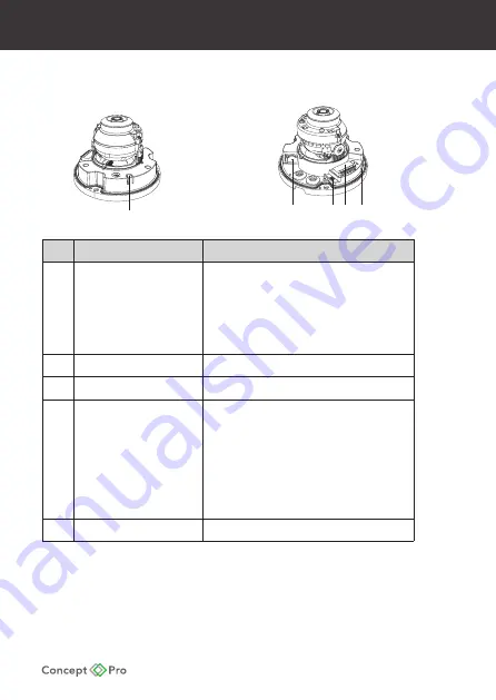
Internal Camera Connections
Item
Name
Description
1
Control Button
Used to change analogue format, restart the
camera, and reset the camera to factory default
settings.
- Change Analogue Format: Press and hold for <5
seconds.
- Restart Camera: Press and hold for >5 seconds.
- Factory Default Reset Camera: Press and hold for
>10 seconds
2
RJ45 PoE/Network
Used to connect network cable between camera
and PoE supply/network.
3
Analogue Service Video
Output
Analogue video output terminal for use during
installation.
4
Audio & Alarm I/O
CVP5325DNIR-IP4M/2.8 only.
AO: Audio Output connection (ex. speaker).
AI: Audio Input connection (ex. microphone).
GND: Ground connection for audio I/O.
COM: COM connection for alarm output.
N.O.: Normal Open connection for alarm output.
RSVD: Not used.
AL 1: Alarm input connection (ex. sensor).
GND: Ground connection for alarm input and
DC12V power input.
12V1: DC12V power input connection if PoE not
used to power the camera.
5
MicroSD Card Slot
Used for Edge storage.
- If using DC12V to power the camera, ensure the power supply matches the camera power
supply requirements specified and connect to the camera DC12V power input.
- Connect the RJ45 connector to a network switch. If the network switch supports Power
over Ethernet (PoE), disconnect any DC12V power connections.
1
2
3 4 5
1
2
3 4 5
Summary of Contents for CVP5325DNIR-IP2M/2.8
Page 12: ......


