background image


Rev.01  03-27-17 

Page 59 of 67 

Compu-Aire


12.0


FACTORY SETTING 


The controller is fully programmed at the factory to meet its specifications.  Adjustments to the 
default settings sometime are required in the field to fine tune the controller to adapt it to the 
environment. 


Note:


A level 3 password is required to gain access to the Factory Menu.  Changes to the 

factory settings are crucial and only recommend for a well-trained technician or under 
factory guidance.


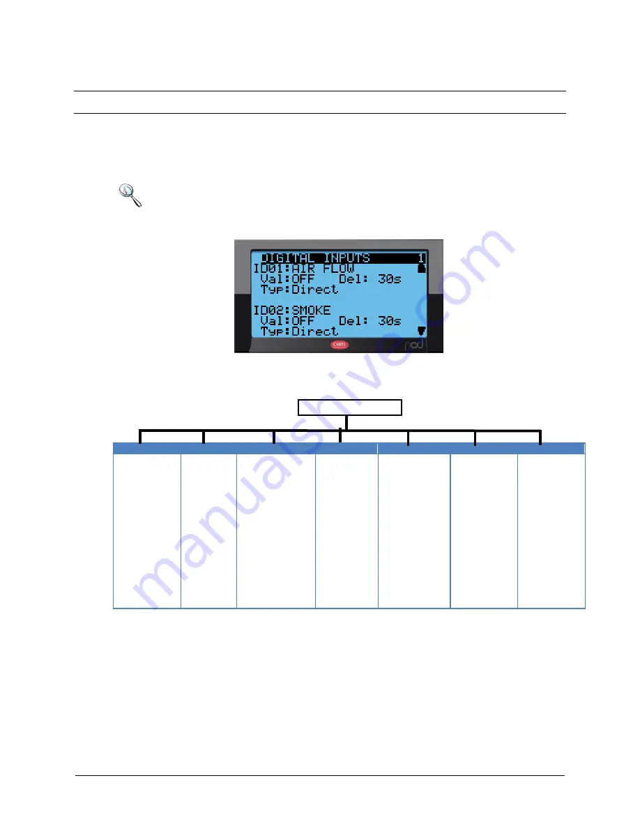
Figure 39 - Factory Setting 

12.1


Factory Setting Menu Tree 

FACTORY MENU 


D. INPUTS 

D. OUTPUTS 

A. INPUTS 

A. OUTPUTS 

HVAC 

PASSWORD 

F. RESET 

Airflow 

Smoke 
Heater OL 

Dirty filter 
Condensate 

Water flow 
C1/2 low pressure 

C1/2 high 
pressure 

Pump failed 
Remote on/off 

Fan overload 
Hum alarm 

Damper proof 
C1/2 overload 

User1/2/3 

Supply fan 

Heater1-5 
Compressor 1 

Compressor 2 
Liquid 1/2 

Unloader 1/2 
HG Bypass 1 

HG Bypass 2 
HG Heat 1/2 

Drain 
Sel alarm 

Global alarm 
Humidifier 

Fan low 
Dehum 


RA temp 

RA hum 
MA temp 

MA hum 
OA temp 

OA hum 
DA temp 

LPT1/2 
HPT1/2 

Efan feedback 
Water in/out 

Air DP 
AVG temp1/2/3/4/5 

Cond. Temp1/2 


Supply fan 

HG Bypass1/2 
Economizer 

Cond. Fan 
HG Reheat1/2 

Chilled water 


Fan Mode 

Fan Delay 
Shut down Fan 

Fan Min/Max ON 
Unit °C/°F 

Compressor Setup 
Economizer 

DX Assist 
Low Pressure Retry 

Dead Bands 
 

Level 1 

Level 2 
Level 3 

Factory Reset 

Op.  Mode 
Reset Alarm Hist. 


Summary of Contents for SYSTEM 2500 S

Page 1: ...Rev 01 03 27 17 Page 1 of 67 Compu Aire SYSTEM 2500 S PROGRAMMABLE CONTROLLER USER MANUAL 8167 Byron Road Whittier CA 90606 Phone 562 945 8971 Fax 562 696 0724...

Page 2: ...mizer Energy miser EM Unit Using 2 Way Valves 13 3 7 Water Cooled Energy Miser 15 3 8 Dry Fluid Cooler with Energymizer 16 3 9 Special Pump and Dry Fluid Cooler control logic 18 3 10 Optional features...

Page 3: ...t 31 8 0 SETUP MENU 32 8 1 Setpoints 33 8 1 1 Changing Setpoints 33 8 1 2 Changing Alarm Setpoints 34 8 2 Clock Setup 36 8 2 1 Time and Date Setup 36 8 2 2 Night Setback 36 9 0 RUN TIME HOUR METERS 36...

Page 4: ...0 3 10 BACnet 48 10 3 11 WARNINGS 48 10 4 BANET over MS TP 49 10 4 1 Installation 49 10 4 2 Meaning of the jumpers 50 10 4 3 Operation 50 10 4 4 Recalling the factory configuration factory bootswitch...

Page 5: ...Rev 01 03 27 17 Page 5 of 67 Compu Aire 12 1 3 Changing Passwords 62 12 2 Factory Reset 62 13 0 TROUBLESHOOTING GUIDE 63...

Page 6: ...7 Temperature alarm setpoints 34 Figure 18 Humidity alarm setpoints 35 Figure 19 Discharge alarm setpoints 35 Figure 20 Shutdown alarms 35 Figure 21 Transducers alarm setpoints 35 Figure 22 Date and t...

Page 7: ...03 27 17 Page 7 of 67 Compu Aire Figure 40 Digital inputs 60 Figure 41 Digital outputs 60 Figure 42 Analog inputs 61 Figure 43 Analog outputs 61 Figure 44 Password management 62 Figure 45 Factory res...

Page 8: ...ilt in navigation keypad and led indicators allowing the users to easily set the controlled parameters for set points dead bands alarm thresholds and carry out the main working operations on off displ...

Page 9: ...onfigured per system configuration Further tweaking may be required to better fit the application Figure 1 User Interface Active alarm Reset alarm Increment Toggle variables Up button Main menu Enter...

Page 10: ...tion icons 1 Shows current time and date Time is showed in military format 2 Shows current room temperature and relative humidity 3 Shows current cooling demand 4 Shows current heating demand 5 System...

Page 11: ...compressor shall be locked out but the system shall provide cooling by other compressor if available On a heater failure the heaters are locked out The system will not use that function until manuall...

Page 12: ...em is equipped with a DX coil compressor s and outdoor air cooled condenser Optional heaters and humidifiers are also available if needed A unique feature of Air Cooled Chilled Water Plus units is tha...

Page 13: ...e energized operating the outdoor air and the return air dampers The economizer damper actuators shall be regulated to maintain proper discharge air temperature When outdoor air is not suitable for ec...

Page 14: ...t before the direct expansion coil and is properly sized to provide the same cooling capacity as the DX system at 45 Deg F entering water temperature The indoor unit will send a signal to enable and d...

Page 15: ...shall control the amount of flow to auxiliary energy miser cooling coils and maintain constant temperature and relative humidity Energy miser systems are connected to Cooling Tower or Dry Fluid Cooler...

Page 16: ...l be arranged for Vertical Air Flow The Glycol Coil shall have aluminum fins bonded to copper tubes and shall have full collars that completely cover the copper tubes The coil shall be pressure tested...

Page 17: ...e and DFC unit will switch over to free cooling energy miser mode In Energy miser mode all other aqua stat aqua stat 2 3 and 4 will be bypassed and all fans will run continuously The free cooling temp...

Page 18: ...ting speed to be maintained should zone loads decrease thus decreasing flow below safe pump operation Outside air temperature reaches 48F Pump controls switch to free cooling mode Fans run 100 until c...

Page 19: ...ommand computer or to an existing building automation system The System 2500S is truly one of the most powerful and flexible controllers available for HVAC units today 4 0 CONFIGURATION The display un...

Page 20: ...be created to customer request CONTROLLER runs the control program and is fitted with the set of terminals required for connection to the devices compressors fans The program and the parameters are s...

Page 21: ...nd touch screen interface 5 3 Mechanical Characteristics SMALL 13 DIN modules 110 x 227 5 x 60mm Plastic container Assembly Fitted on DIN rail as per DIN 43880 and IEC EN 50022 Material techno polymer...

Page 22: ...ms device status indicators and remote switches Digital inputs are not optically isolated and have voltage free connects Figure 6 Digital inputs Note Separate as much as possible the probe and digital...

Page 23: ...0mA voltage inputs dry contact or PWM Maximum number of analog inputs that can be connected to the universal inputs outputs depends on the type used WARNING The 21VDC available at the Vdc terminal J2...

Page 24: ...ded cable 200m 150mA from CONTROLLER AWG20 22 shielded cable 500m Separate power via TCONN6J000 The maximum cable length between the two controllers using AWG20 22 shielded cable is 500 meters Note A...

Page 25: ...v 01 03 27 17 Page 25 of 67 Compu Aire 5 10 Standard Input Outputs The following table defines standard I O ports for the System 2500 controller Refer to the electrical wiring diagram for actual wirin...

Page 26: ...LAN network that operates as a single entity enhancing the already high performance and efficiency of units System 2500 controllers are available as factory installed assembly Remote console box with...

Page 27: ...demand 4 Heating demand 5 System status 6 Mode of operation 7 Blink menu Table 4 Status Info 7 0 Navigation Menu The controller s menu is organized under different categories Each category may require...

Page 28: ...nded without consulting factory Press the menu button to gain access to menu function Figure 9 Menu tree Main Menu I Setpoint a Temperature Cooling Heating b Humidity c Discharge If applicable d Dehum...

Page 29: ...scroll through the icons page by page To scroll through the icons one by one press the enter key then use the up and down arrow keys Note Viewing settings require a password Level 1 Password 1 Leve2...

Page 30: ...d cooling demands Additional sensors are listed by pressing the up or down buttons Icon Function Demands Displays Fan cooling heating humidification dehumidification excess humidity draining and humid...

Page 31: ...the alarm history under setup to view the remaining alarms Action Function Alarm Pressing the alarm button at any time Next Shows the next alarm Previous Shows previous alarm Reset Press and hold the...

Page 32: ...uired to view system status active alarm or turning the unit ON OFF System is automatically locked out after 5 minutes of inactivity and returned to the main screen A new password must be entered to r...

Page 33: ...65 35 Discharge temp 55 F Water in Econ 50 F 8 1 1 Changing Setpoints Press menu and navigate to setpoint The cursor is shown on the upper left of the screen Move the cursor to the setpoint by pressin...

Page 34: ...The alarm High and Low setpoints trigger an alarm event when the room returns temperature falls below or exceed the set limits To gain access to alarm setpoints Menu Technician Alarm Setup Figure 17...

Page 35: ...Rev 01 03 27 17 Page 35 of 67 Compu Aire Figure 18 Humidity alarm setpoints Figure 19 Discharge alarm setpoints Figure 20 Shutdown alarms Figure 21 Transducers alarm setpoints...

Page 36: ...s take effect immediately and require no system reset 8 2 2 Night Setback The controller supports 7 days unoccupied and occupied modes Separate temperature and humidity setpoints are available and tak...

Page 37: ...Rev 01 03 27 17 Page 37 of 67 Compu Aire Figure 23 equipment run hours Reset counter counter...

Page 38: ...menu is only applied for Modbus protocol Other protocol required separate software interface Consult factory for more information Default Setting Unit Identification 1 Baud Rate 19200 Protocol Modbus...

Page 39: ...electrostatic discharges from the operator Suitable precautions must be taken when handling these components Before using any electronic component or card ground yourself not touching the card does n...

Page 40: ...pending on the model the interface boards communicate via two physical channels TP FT 10 and TP RS485 39 as described in the LonWorks literature The LONTalk card uses an Echelon FTT 10 transceiver app...

Page 41: ...ON BAUD RATE ON THE PCO HAS BEEN SET TO 4800 BAUD 10 2 5 Installation WARNINGS precautions in handling the board Electrical damage may occur to the electronic components as a result of electrostatic d...

Page 42: ...tocol at 4800 baud the red LED on the board will come on for a few seconds and then will go off immediately indicating normal operation Figure 27 Remove plastic cover Figure 28 Cut out window Figure 2...

Page 43: ...onWorks network This generates an event that the application on the specific node can respond to with any action decided by the programmer In this specific case the service LED on the interface comes...

Page 44: ...ctrical panel near the controller so that the MAC ADDRESS can be read without needing to open the electrical panel for the connection to the Ethernet network use an S FTP cable category 5e or higher 1...

Page 45: ...with the status LED flashing regularly press and hold the button for between 5 and 10 seconds after around 10 s from releasing the button the status LED will stop flashing and after a further 15 seco...

Page 46: ...ng the IP address of the pCOWeb in the address bar will access the default home page of the pCOWeb Then enter the area reserved for the administrator using the special link Go to Administrator Area an...

Page 47: ...gistered User Name Description Default Password Allowed root administrator of the operating system froot no limitation httpadmin web administrator Fhttpadmin R W access to the http directory read only...

Page 48: ...ateway between the controller proprietary protocol and BACnet The information transferred involves all the data sent to the supervisor by the application loaded on the controller The parameters relati...

Page 49: ...operation may be complex as a result insert the PCOnet card at an angle then tilt it back until the connectors line up 3 Insert the required jumpers see below for the meanings of these 4 Fit the cover...

Page 50: ...e 7 10 4 3 Operation The Status LED left indicates the status of communication with the controller and the status of the PCOnet Starting sequence on power up or after restarting PCOnet the Status LED...

Page 51: ...PCOnet keeps the Token control of the MS TP network green OFF PCOnet DOES NOT keep the Token red on Poll For Master search for a Master to pass the Token to Green and red ON together BACnet MS TP mea...

Page 52: ...confirms recognition of the button by flashing QUICKLY 3 times red off and then comes on green again Complete start up of the PCOnet will take another 40 seconds then the RS485 LED starts flashing on...

Page 53: ...units Max Master should be set to the Station Address of the Master with the highest Station Address In fact each Master after having used the network passes over control to the next Master The Max Ma...

Page 54: ...rk CLAN network setup Manual Control Manual control for each components Table 12 Technician menu description 11 1 Alarm Setup The controller supports a general alarm or global alarm for the following...

Page 55: ...F Configuration R2 SW Dirty Filter Alarm OFF OFF Sensor Failure Alarm OFF ON Drain Full Alarm OFF OFF Fire Stat Alarm OFF OFF Note Not all systems are equipped with a general alarm or global alarm Set...

Page 56: ...larm Temperature reaches 125 F Table 13 Global alarms The alarm status is notated by its current setting To set the alarm change the setting to either ON OFF by tapping the screen and toggling via the...

Page 57: ...lt Setting Offset 0 11 2 Network Setup The controller supports up to 32 units working together as single unity in a pLAN network A pLAN network composes of one 1 master unit with up to fifteen 32 slav...

Page 58: ...digital outputs are selectable as ON OFF or AUTO mode The following components are available in the manual setting Note Do not use this option to permanently turn off components such as reheat or humi...

Page 59: ...TPUTS HVAC PASSWORD F RESET Airflow Smoke Heater OL Dirty filter Condensate Water flow C1 2 low pressure C1 2 high pressure Pump failed Remote on off Fan overload Hum alarm Damper proof C1 2 overload...

Page 60: ...factory prior to shipping Changes are not recommended unless suggested by the factory Consult the factory for more detail In general the controller works with a 24VAC input from the normally opened r...

Page 61: ...input sensors are used for monitoring room temperature and humidity NTC and transducers are also supported Analog output terminals are primarily used for economizer systems where modulating output si...

Page 62: ...ttings Pwd change Figure 44 Password management User Access to status and setpoints Service Access to technician menu Manufact Access to factory settings Web access Access to web based interface 12 2...

Page 63: ...Rev 01 03 27 17 Page 63 of 67 Compu Aire 13 0 TROUBLESHOOTING GUIDE...

Page 64: ...omply with standard and not exceeding 1000 meters Speed Make sure computer and controller are set to the same speed Default speed on the CONTROLLER controller is 19 2k Add on card not installed proper...

Page 65: ...Temperature drops below min setpoint Room is too cold Check sensor and reset alarm after fixing the problem High Humidity Humidity rises above max setpoint Too much moisture in the air Check and reset...

Page 66: ...and reset alarm after rectifying the problem Condensate Alarm Water detected Check for water level on the bottom tray Check drain valve and reset alarm after rectifying the problem Pump failed Conden...

Page 67: ...7 Page 67 of 67 Compu Aire TECHNICAL SUPPORTS www compu aire com Tel 562 945 8971 Fax 562 696 0724 UNITED STATES OFFICE Compu Aire Inc 8167 Byron Rd Whittier CA 90606 SUBJECT TO CHANGE WITHOUT INCURRI...

Reviews: