Composite-ARF IMPACT F3A-type Instruction Manual Download Page 16

plastic nuts until cured. Open up the milled holes in the back of the root ribs of both wings so
that the short 12mmØ carbon tubes fit in easily. Wax both ends of the 10mm anti-rotation tube
where it projects outside the fuselage, the inside surface of the 2 short 12mmØ carbon tubes,
and the outside of the fuselage in this area. Sand the outer surface of the tubes to prepare for
gluing.

With the fuselage still set with the stabs at exactly 0° check the incidence of the wings. If you
milled to marked hole positions accurately on the marks set during manufacture you will find
that the wings are between 0° and +0.5° incidence. Nominally the correct incidence should be
about +0.25°. Adjust the position of the hole in the root rib until you get one wing set correctly,
apply a very thick 30 min epoxy/microballoon mix to the outside of the 12mm carbon tube and
push the wing fully into position. Secure with the plastic nut until completely cured (min. 2 hrs)

After both wing incidences are finally set correctly, remove the wings and check the glue joint
around the carbon tubes. Apply more epoxy mix as needed to secure properly.

0° -  0° Datum line:

While C-ARF prefer and advise to use the above method for setting the incidences, as an
alternative, you can use the horizontal 0° datum line of the fuselage to set the stab and wing
incidences. This imaginary line is positioned from the 

front

edge of the cowl to fuselage joint,

to a dimension of exactly 37mm below the centreline of the 10 mmØ stab tube.

While the fuselage is set up with the stab at 0° you can also check the vertical front face of the
fuselage for the downthrust angle which should be between -2° and -2.5°.

Now you can go on to complete the wing and
stab servos and linkages as follows.

Horizontal Stabs

The stabs are 95% finished at the factory and
are elastic-hinged during manufacture, so you
only need to install servos, horns and linkages. 

Glue a 20mm length of hardwood dowel into
both ends of the carbon stab tube with epoxy
and microballoons mix. Inside the stabs you will
see a small plywood reinforcement plate
between the carbon spar sleeve and the bottom
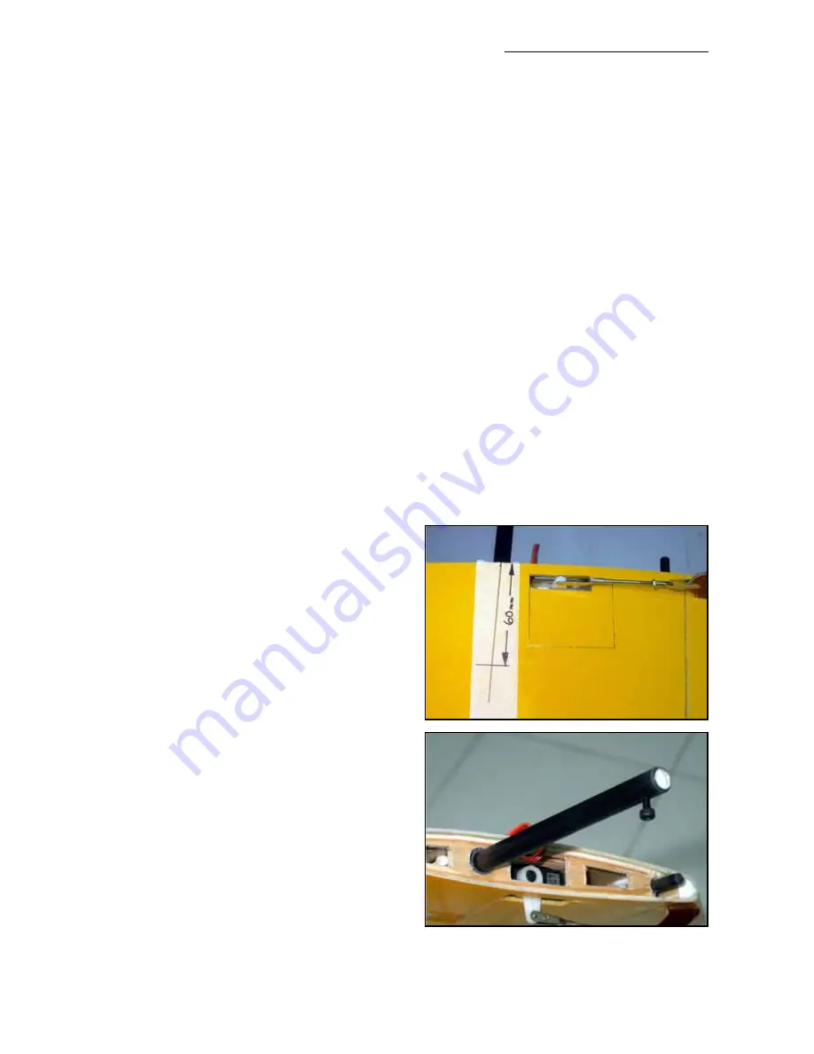
surface of the stab. Mark the bottom of both
stabs exactly in line with the centre of the carbon
tube, and in this ply plate. Nominally the centre
of the plate is 60mm from the root rib.

Install the carbon spar tube fully into 1 stab, and
drill a 2.4mm hole through the stab, the plywood
plate, sleeve and into the centre of carbon spar
tube. You will need to drill 15mm deep. Do NOT
drill right thru’ the stab tube - only through one
side of the tube into the hardwood dowel. Tap
M3, and counterbore the hole in the underside of the stab so that the M3 x 12mm bolt fits flush
with the surface and bears on the plywood plate - NOT on the composite stab structure.

Composite-ARF IMPACT

[email protected]

16

Summary of Contents for IMPACT F3A-type

Page 1: ...techsupport composite arf com Composite ARF IMPACT Instruction Manual Composite ARF IMPACT TAVS Technology version 1 0...

Page 2: ...rescribed by binding law the obligation of the Composite ARF compa ny to pay compensation is excluded regardless of the legal argument employed This applies to personal injury death damage to building...

Page 3: ...ing tips before you start the engine Make sure that all spectators are behind or far in front of the aircraft when running up the engine Make sure that you range check your R C system thoroughly befor...

Page 4: ...of the wing not in the centre This is NOT a disadvantage if you program in about 10 NEGATIVE aileron differential in your transmitter This means that the down throw needs to be about 10 more than the...

Page 5: ...ered by a single JR8411 servo or similar in the fuselage with a closed loop system Take Care Composite sandwich parts are extremely strong but fragile at the same time Always keep in mind that these c...

Page 6: ...nge but the result is extraordinarily impressive Even with slight flaws the general appearance of these one of a kind paint jobs is unique In a positive paint job some effects can never be done Just t...

Page 7: ...ease don t use inferior quality glues you will end up with an inferior quality plane that is not so strong or safe Note Especially with the sandwich laminates the use of CA adhesives requires extreme...

Page 8: ...PACT The new Composite ARF IMPACT is not really an ARF like our other planes It is not a beginners model and not a trainer We expect some experience in building and flying with this type of contest pl...

Page 9: ...to prepare the inside of the fuselage properly by roughing up and cleaning the surface with alcohol before gluing any parts to it Epoxy glues will not stick properly to any surface that has not been...

Page 10: ...hru the centre of the ply squares 3 2mm and tap M4 Fit the plastic bolts and mark the position of the heads of the bolts on the fuselage flanges Reposition these marks about 10mm forward and drill 2 h...

Page 11: ...for some electric power installations this will need to be closed later for correct cooling and you can use some thin balsa sheet or foam board for this Cut out the 2 rectangular holes in the sides o...

Page 12: ...the fuselage Glue the 15 x15mm ply plate inside the canopy flange and drill and tap M4 as before Fit the plastic bolt and transfer the posi tion to the flange on the fuselage Mark a centre point 9mm...

Page 13: ...nd U plate Result a perfectly fitting canopy that will not rattle and definitely cannot come off in flight when you fit it as described above Paint the canopy as you like Wing and Stab Alignment For y...

Page 14: ...les a little if needed Don t worry about wing and stab incidences at this point and don t adjust the holes for the anti rotation tube pins Now fit the carbon wing anti rotation tube with its rein forc...

Page 15: ...fect fit apply a layer of paper tape to the sides of the fuselage to protect it and use a strip of 240 grit sandpa per between the fuse and roots for fine adjust ment see photo Use the same technique...

Page 16: ...nd wing incidences This imaginary line is positioned from the front edge of the cowl to fuselage joint to a dimension of exactly 37mm below the centreline of the 10 mm stab tube While the fuselage is...

Page 17: ...with a sharp knife to allow the horns to be glued into the slots This stops excess glue getting on the surface of the elevator Adjust the slots in the elevators so that the holes for the clevise are e...

Page 18: ...talling Install the milled phenolic horns into the ailerons in exactly the same way as the elevator horns described above The servos are installed in the composite rib with a plywood doubler on the ba...

Page 19: ...n the rudder with a Dremel and 2mm milling tool for the supplied phenolic Rudder horn The slot should be 52mm 2 up from the bottom of the rudder The front of the slot should be against the back edge o...

Page 20: ...der and fin post in the fuselage properly Do NOT use CA to glue the hinges into the rud der or fin post If this hinge becomes loose and you have rudder flutter this can damage or destroy the back of t...

Page 21: ...e a few of your own No engine mounting hardware is included in the kit because of the many different set ups and engine choices Glow or Gas engine installation Included in the kit is a generic composi...

Page 22: ...cohol and glue the firewall in with slow epoxy and milled fibre mixture The front face of the fuselage is already moulded with between 2 2 5 degrees of downthrust and sidethrust which will be close en...

Page 23: ...n balsa sheet or similar to complete the pipe compartment Cut a large enough exit hole in the bottom of the fuselage for the warm air to exit from the pipe compartment and extend the outlet of your pi...

Page 24: ...Ignition System If you are fitting a gas engine we advise that you keep the ignition unit as far away from the receiver and R C equipment as possible Generally you will be able to mount the ignition...

Page 25: ...iver to prevent any chance of R C interference which can occur when using a BEC system or a voltage regulator to use current from the Flight pack for the receiv er In this case we used a 4 cell 600mAH...

Page 26: ...the motor and glue both bulkheads in position properly with slow epoxy and milled fibre mixture Slight thrust line changes can be made after trimming flights by adjusting the holes in the 3 plywood ea...

Page 27: ...AH were mounted in a similar way as for the Hacker with a small piece of foam board glued onto the carbon tubes which are glued to the fuselage sides and reinforced with the milled carbon ply rings su...

Page 28: ...knife and glued in place with CA This is very important as any wires or insu lating material rubbing on the edges of compos ites will be cut thru in 1 flight which can cause a dangerous short circuit...

Page 29: ...m mend Do NOT leave your LiPo batteries un attended during charging Important When installing the battery ies in the model before a flight make sure that no con nectors can touch each other and cause...

Page 30: ...plit silicone tubing Make sure that no fuel tubing or wires can come into contact the hot exhaust or speed controller heatsink Did you fit short Tygon or silicone tube pieces over all the clevises Did...

Page 31: ...packing your engine mount as needed Control Throws All measurements are at the root trailing edge position Elevator All controls should be set with a dual rate switch On high rate the elevator should...

Page 32: ...ail feedback composite arf com Thank you Your Composite ARF Team Flying and Trimming During your first flight you should get a feel for the plane and then set your control throws for your liking The o...

Page 33: ...ge your trim setting at this time land and adjust the thrust line accordingly After adjustment make another test flight to see if it improved You should stop when the plane in vertical up AND down lin...

Page 34: ...g the pull your right elevator might travel a bit more than the left one or your right wing might be a little bit heavier than the left one If it turns to the left it is vice versa Please try it many...

Page 35: ...bon pins for chin cowl mounting 6mm x 30mm 2 Carbon tubes for chin cowl mounting 8mm x 20mm 1 Carbon tube for stab tube 12mm x 45mm 1 Carbon tube stab spar 10mm x 190mm 1 Anti rotation rod carbon rod...

Page 36: ...ctric Power option pack bulkheads etc Hacker C50 geared motor Master 0 90 Acro Speed controller Plettenberg Xtra 25 13 motor Schulze future 32 55 Speed controller Set 4mm Gold connectors 10 each male...

Page 37: ...Composite ARF IMPACT techsupport composite arf com 37 Impact fuselage tail formers Make from 3mm balsa Mike Cherry 8 Dec 2004 Mac...

Reviews: