ADCP-96-806 • Issue 4 • July 2016
Page 5
© 2016
CommScope
. All Rights Reserved.
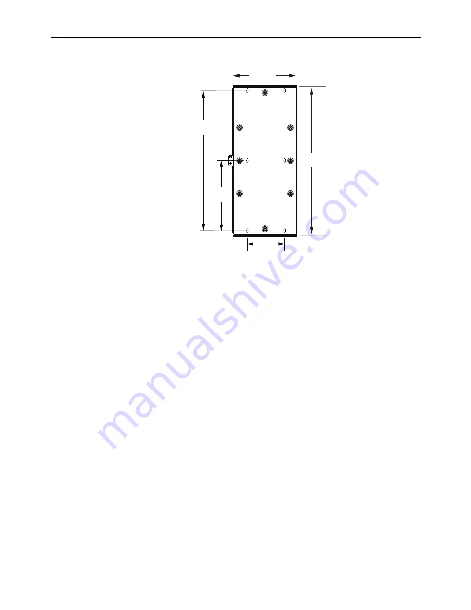
Figure 2. Cabinet Dimensions
4. Using the template as a guide, drill pilot holes for the six 3/4-inch #10 panhead screws
required for mounting the cabinet.
5. Partially install the
top
two
#10 wood screws leaving the heads protruding about 1/4-inch
from the surface of the backer board.
Do not tighten.
6. Hang the cabinet on the two installed screws using the key-hole shaped slots.
7. Level the cabinet, tighten the two top screws, and then install the remaining #10 screws.
3
GROUNDING THE CABINET
This section provides instructions for connecting a grounding wire to the cabinet. Use the
following procedure to ground the cabinet:
1. Locate the grounding components that are provided separately with the cabinet. A
grounding lug kit (consisting of two external tooth washers, two nuts, one screw and one
lug) is provided.
2. Open the hinged middle-section of the cabinet to provide access to the cabinet’s
termination and splicing compartment.
3. Threaded inserts are provided on the left and right sides of the cabinet. Select one of the
inserts for installation of the grounding components.
4. Install the required grounding components as shown in
and studs to 40 inch-lbs (4.5 Nm) of torque.
5. Use a #6 AWG copper wire to connect the cabinet to an approved earth ground source as
specified by local code or practice. Avoid sharp bends in the ground wire.
8
IN
(20.3 CM)
15 IN
(3
8
.1 CM)
30 IN
(76.2 CM)
13 IN
(33.0 CM)
32 IN
(
8
1.3 CM)
BACK
OF
CABINET
23116-A


