ADCP-96-167 • Issue 5 • July 2016
Page 49
© 2016, CommScope, Inc.
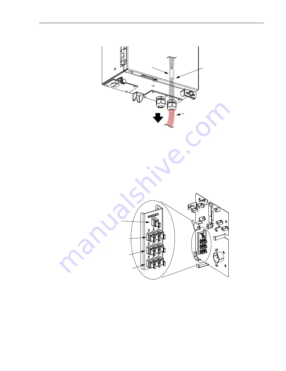
Figure 44. Install MPO Cables in Grommet
8. Pull on the MPO cables from the outside of the cabinet until the end of the
grommet is flush with the compression nut opening.
9. Locate the adapters on the bulkhead adapter panel that are designated for the
feeder cable and distribution cables. The layout of the bulkhead adapter panel is
shown in
.
Figure 45. Layout of Bulkhead Adapter Panel
10. Route the first MPO cable to the bulkhead adapter panel as shown in
There should be sufficient slack to wind the cable two times around the radius
limiters before routing the cable to the bulkhead adapter panel. If necessary, slack
may be removed/added by pulling the cable in/out of the cabinet through the
grommet.
24336-A
MPO
CABLES
WHEN CABLES HAVE BEEN
INSTALLED IN GROMMET, PULL
ON CABLES TO DRAW GROMMET
INTO COMPRESSION FITTING
COMPRESSION
FITTING GROMMET
PLACE BOTTOM OF
GROMMET 36 INCHES
FROM END OF MPO
CONNECTORS
24347-A
*FEEDER
CABLE
DISTRIBUTION
CABLE CONNECTORS
1 - 3
DISTRIBUTION
CABLE CONNECTORS
4 - 6
DISTRIBUTION
CABLE CONNECTORS
7 - 9
DETAIL OF BULKHEAD
ADAPTER PANEL
*THE SPLICE/MPO CONNECTOR
CABINET DOES NOT HAVE A
FEEDER CABLE CONNECTOR


