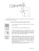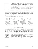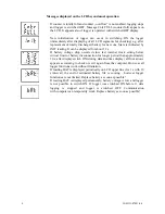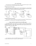
•
check free space in data memory, optionally erase data memory of the logger
•
enter password if protection against unauthorized manipulation with the logger is necessary
Logging interval between to subsequent measurements is specified by the user. Memorizing of the
first value is synchronized with the internal real time clock, so the logging is performed at sharp
multiples of minutes, hours and days. E.g. after starting the logging with the 15 minute interval the
first value is not stored immediately, but after the internal clock gets the status of a quarter, a half or
a whole hour. After starting the logging with the 6 hours interval the first value is stored at that
whole hour to perform the storing also at 00.00, i.e. at the beginning of the day. First storing is
performed at 6.00,12.00, 18.00 or 00.00hour - at the hour from the above nearest to the logging
start. After communication with computer or after start by magnet logger automatically waits for
the nearest whole multiple of time and then first measurement is performed. This is also necessary
to take into account when setting time of automatic logger switch ON.
Notice:
If logger operates as permanently connected to the computer, using of magnet
start/stop is disabled.
To enable the logger control by magnet is suitable only in cases, when possibility of
unauthorized manipulation to the logger operation is eliminated.
If logger is controled by external signal (i.e. by binary state at input 4), logger will be switched
OFF (when programmed binary state at input 4 appears) with the delay up to 10 s!
User description of binary states is displayed only at the data list on the computer. On the
logger LCD indication ON and OFF is displayed permanently.
Selection of „display of increments“ at the card of counter channel setting causes record of
counter increments in time specified by logging interval. On the logger LCD counter values are
displayed (not increments).
Logger connection to monitored devices
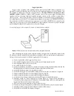
Connect logger to monitored device by shielded cable with 9 pins female CANON connector.
If IP67 protection is required, it is necessary to use watertight connector (optional accessory).
Channel 1 of the logger (IN1) works as counter at pin 6 of the connector, channel 4 works as binary
input at pin 1 of the connector. Both inputs have common ground (GND) at connector pins 5 a 9.
Those pins serve for connection of the cable shielding. As monitored signal use quality mechanical
contact (reed contact) or device with „open collector“ or device with binary voltage output. Due to
high input impedance it is necessary to avoid presence of increased electromagnetic interference
(e.g. electric switchboards, motors, device containing power current switching elements -
contactors, relays or pulse converters etc.).
If logger will be controlled (switch ON and OFF) by external binary signal, connect output of
the control device to pin 1 (input 4 of the binary channel) and pin 5 (signal ground). It is necessary
to allow selection „Logger control by external signal“. At the same time set required binary level
for logger switch ON at the card of channel 4. In switching ON by external signal logger reacts
immediately, in switching OFF reacts with delay of maximum 10 s.
Notice:
pin 9 is galvanic connected to pin 5 (both GND). If other signal source is used than
potential-less mechanical contact, note, that signal grounds of both channels will be connected
together – grounds of both devices must be mutually galvanic isolated or must be at the same
potential!
IE-LOG-S7021-04
5


