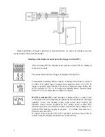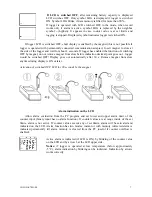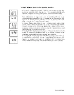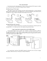
Minimum pulse duration at binary input: 500 ms (shorter pulses may not be recorded)
Maximum frequency at binary input: 0.5 Hz (i.e. maximum 5 pulses in 10 s)
Current through closed contact: 3
µ
A
Voltage across opened contact: 3.6 V
Low voltage level: 0 to +0.2 V (maximum current from input 3
µ
A)
High voltage level: +3.0 to +30 V (maximum current to input 100 nA)
Built-in connector for input signals: male CANON 9 pins
Cable for connection of input signals: shielded, maximum length 10 m
Alarm evaluation interval and display refresh: 10 s
Logging interval: 10 s to 24 h (20 steps)
Memory capacity:
counter mode 16 bits:
non-cyclic logging mode
32 504 readings
cyclic logging mode
28 896 readings
counter mode 32 bits:
non-cyclic logging mode
16 252 readings
cyclic logging mode
15 296 readings
Specified values are maximum possible and can be reached only if record since last
memory erasing was not interrupted and no event on binary inputs was recorded. Each
event record on the binary input decreases above capacity of one record.
Communication with computer: via RS232 (serial port) by means of COM adapter or USB
port by means of USB adapter; data transfer from logger via communication adapter is
optical
Real time clock: adjustable from computer, integrated calendar including leap years
Error of internal RTC: < 200 ppm (i.e. 0.02 %, 17.28 s in 24 h)
Power: Lithium battery 3.6 V size AA
Battery life:
typical (data download to PC is carried out about once a week): 3 years
in continuous on-line mode with interval 1 minute: approximately 2 years
in continuous on-line mode with interval 10 seconds: approximately 1 year
Notice: The above battery lives are valid for logger operation in temperature from -5 to
+35°C. If often operated outside of the above temperature range battery life can be reduced
to 75%.
Protection: IP67
Operational conditions:
Operational temperature range: -30 to +70 °C
Operational humidity range: 0 to 100 %RH
Specification of outer characteristics accordingly to EN33-2000-3: normal environment
accordingly to appendix NM: AE1, AN1, AR1, BE1
Operational position: negligible
Logger installation: by self adhesive Dual Lock, applied to clean, flat surface
Not allowed manipulation: it is not allowed to operate instrument with not connected
temperature probes - if all probes are not connected, unconnected connectors should be
protected by included connector cover.
Limit condition: temperature -40 to +70 °C, humidity 0 to 100 %RH
Storing condition: temperature -40 to +85 °C, humidity 0 to 100 %RH
Dimensions: 93 x 64 x 29 mm
Weight including battery: approximately 120 g
Material of the case: polycarbonate
IE-LOG-S7021-04
3


