Instruction for use of logger S7021
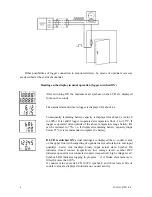
Logger is designed for monitoring and record of digital signals from external devices. It is
equipped with input for pulse counting and binary input for record of time event. Signals are
connected by means of the connector. Counter reading and actual state of binary input are displayed
on dual line LCD are stored in adjustable interval to internal non-volatile memory. Input pulse
signal is recalculated and displayed in real measured physical units by means of the PC software.
All logger setting and control are done by means of the computer and can be protected by password.
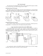
Logging start/stop is enabled: at certain time and date programmed from computer, by external
signal connected to binary input or by delivered magnet). Switching ON and OFF is enabled also by
external binary signal of channel 4.
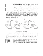
It is also possible to operate logger with switched OFF display. Short display of actual
measured values is enabled by means of magnet.
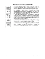
Switched ON logger every 10 s (independently on programmed logging interval) updates
display reading, compares counter reading with two adjustable limits and indicates alarms on the
display. Two alarm modes are enabled: instant or with memory (detected alarm is indicated
permanently till alarm memory is cleared from the PC – useful if counter overflow is enabled).
Alarm function can be enabled or disabled. Binary channel has no alarm function.
Counter can be configured as 16 bits (higher maximum number of recorded values) or 32 bits
(higher counter range). Counter stops after filling the maximum value and logger is switched OFF
with the message on the LCD. If needed counter mode can be selected, when after fulfilling counter
overflows and continues from value 0.
Logging mode can be adjusted as non-cyclic, when logging stops after filling the memory. In
cyclic mode oldest stored values are overwritten by new. In addition logging mode can be selected
when logging is active only if measured value is out of adjusted alarm limits.
Stored values can be transferred from logger memory to the PC by means of communication
adapter. Communication adapter can be connected to the logger permanently – data logging is not
interrupted even if data download appears.
Logger evaluates minimum battery voltage and its drop below allowed limit is indicated on the
display. At the same time value of remaining battery capacity is available by means of the PC
program and appears on the logger LCD in % (every time after switch ON).
Technical parameters of the instrument:
Counter input (logger channel 1):
Counter range: in 16 bits mode 0 to 61 695 values
in 32 bits mode 0 to 2 021 654 527 values
Maximum counter value displayable on the LCD: 19999, 0 to 3 digits right from decimal
point
Signal for counter input: from potential-less contact or binary voltage signal
Minimum pulse duration at counter input: 1 ms (shorter pulses may not be recorded)
Maximum frequency at binary input: 500 Hz
Current through closed contact: 30
µ
A
Voltage across opened contact: 3.6 V
Low voltage level: 0 to +0.2 V (maximum current from input 30
µ
A)
High voltage level: +3.0 to +30 V (maximum current to input 100 nA)
Incrementing of counter: by leading edge (by contact opening)
Binary input (logger channel 4):
Signal for binary input: from potential-less contact or binary voltage signal
2
IE-LOG-S7021-04


