Manuel d’utilisation et d’entretien
Betriebs-und wartungshandbuch
Pag.23
TD 302
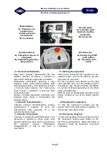
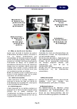
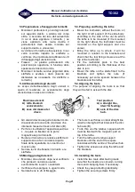
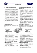
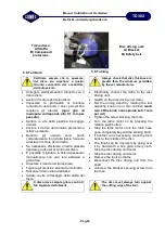
5.6.Impostazione del tornietto sul disco
5.6.Setting the lathe on the disc
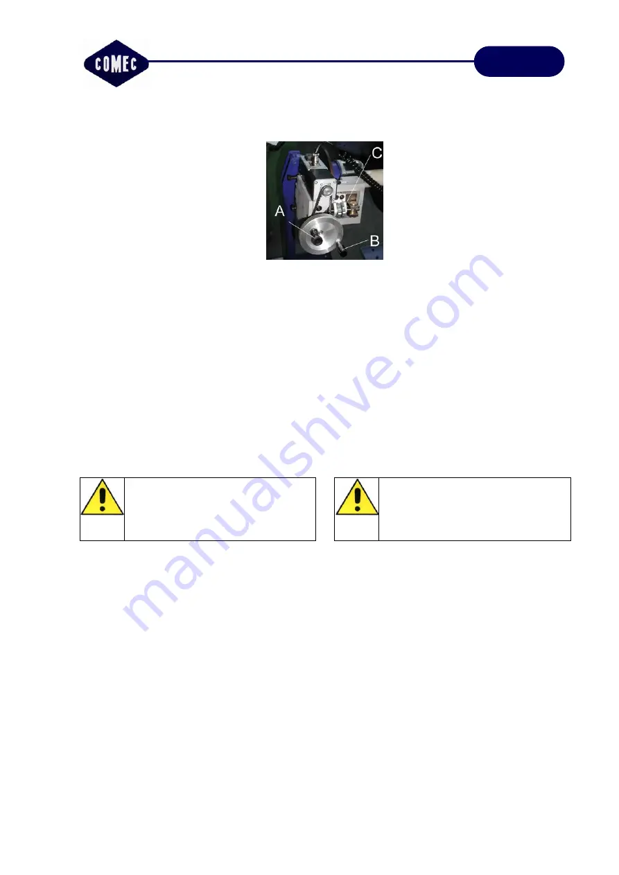
Tornietto:
A) Manopola per
scollegamento cinghia;
B) Volantino;
C) Manopole regolazione
degli utensili.
Lathe:
A) Knob for
disconnecting the belt;
B) Handwheel;
C) Tool adjusting knobs.
Tirare verso fuori la manopola (A),
evidenziata in figura, e ruotarla di ¼ di giro
in modo tale da rendere folle il pignone di
collegamento
con
la
cinghia
del
motoriduttore.
Ruotando il volantino portare gli utensili
nel punto in cui inizia la tornitura. (la
tornitura si fa dal centro del disco verso
l’esterno)
Allentare la vite della piastrina che blocca i
portautensili.
Ruotare le manopole di regolazione degli
utensili fino a far sfiorare le punte degli
utensili alle facce del disco da tornire.
Riposizionare la manopola (A) in posizione
di aggancio cinghia.
Pull knob (A) outwards, as shown in the
figure, and turn it ¼ of a turn so the pinion
connecting to the geared motor belt is idle.
Turning the handwheel, bring the tools up
to the point where turning starts (turning is
done from the centre of the disc working
outwards).
Loosen the screw of the toolholder locking
plate.
Turn the tool adjusting knobs until the tool
points just brush the face of the disc to
turn.
Put knob (A) back into the belt hooking
position.
Se il disco presenta un bordo
esterno molto pronunciato, è meglio
all’inizio portarsi in prossimità del
bordo ed eseguire manualmente la
tornitura con gradualità.
In the case of marked rims on disc
faces, it is advisable to start by
turning the rims manually and
gradually.
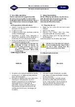
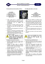
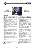
5.7.Applicazione del traino disco
Montare la staffa su una vite del mozzo
avendola prima applicata all’asse con i
giunti cardanici.
Infilando la mano sotto la campana
protettiva, allentare il volantino che fissa la
staffa e centrare l’asse sulla staffa in modo
che esso ruoti in asse con il mozzo.
Serrare il volantino.
Inserire l’asse nel foro del riduttore a
destra o a sinistra a seconda del senso di
rotazione voluto (orario o antiorario).
Il
disco dovrà ruotare contro l’utensile.
Avvitare il relativo pomello di bloccaggio
dell’asse ed inserire la spina nella presa di
alimentazione elettrica e connettere il
tornietto.
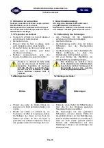
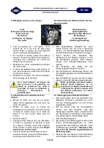
5.7.Disc driving unit attachment
Mount the bracket on one screw of the hub
after first having attached it to the axle with
universal joints.
Putting your hand under the safety bell,
loosen the handwheel securing the
bracket and centre the shaft on the
bracket so it will turn in axis with the hub.
Tighten the handwheel.
Insert the shaft into the hole of the geared
motor, on the right or left according to
rotation direction (clockwise or counter
clockwise).
The disc must turn against
the tool.
Screw down the relative shaft locking
knob, put the plug in the mains socket and
connect the lathe.
Summary of Contents for TD 302
Page 33: ......


