16
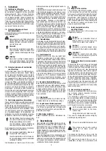
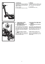
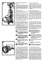
7.2 Montage des Flüssigkeitstanks
(Bild 9)
Tank (A) je nach Höhe des Motors in die obere
oder untere Steckvorrichtung (9) an der Füh-
rungsstange (8) einstecken. Oberen Teil des
Tanks fest gegen die Führungsstange drücken,
so dass die Schnappverbindung (B) einrastet.
Mit dem Schwenkbügel (E) gegen Lösen
sichern.
Bowdenzug einhängen
Ösenende des Bowdenzuges in den
Haken (6) des Dosierhebels (5) einhän-
gen.
Freihängenden Bowdenzug mit der Hül-
se (C) in seitlichen Halteschlitz (7) am
Schaltergehäuse (4) einklemmen. Mit
Stellschraube (D) den Bowdenzug so ein-
stellen, dass sich das Ventil durch Zie-
hen des Dosierhebels (5) öffnet und
nach dem Loslassen wieder vollständig
schließt. Während des Arbeitens wird
das Sprühmittel durch Ziehen des
Dosierhebels (5) hinzugegeben.
Klarsichtschlauch (F) in die Bohrung, bzw.
auf den Schlauchnippel (14) am
Maschinenkörper (16) fest einstecken.
Bei der Maschine E 250 muss vorher der
Kunststoffstopfen auf dem Maschinen-
körper (16) entfernt werden.
Durch Absenken der Führungsstange (8) den
Tank (A) in eine optimale Einfüllstellung brin-
gen. Reinigungsflüssigkeit in den Tank einfül-
len (Bei E 250 max. 6 Liter; bei E 400 S, E 500
S/E und E 430 max. 15 Liter). Während des
Arbeitens wird die Reinigungsflüssigkeit durch
Ziehen des Dosierhebels (5) hinzugegeben.
Keine Flüssigkeiten einfüllen die hei-
sser als 40° C sind ! V erwenden Sie
nur vom Gerätehersteller empfohlene
Reinigungsmittel.
Auf keinen Fall dürfen Reinigungsmit-
tel verwendet werden, welche leicht
entzündbare, brennbare, giftige, ge-
sundheitsschädigende, ätzende oder
reizende Stoffe enthalten.
Die maximale Füllmenge nicht über-
schreiten! Die Maschine kann sonst
umkippen.
9
10
7.3 Montage des Sauggerätes
Das Sauggerät ist nicht zur Absaugung
gesundheitsschädlicher und/oder nas-
ser Stäube geeignet!
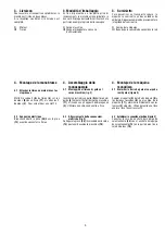
7.3.1 Montage des Absaugringes (Bild 10)
Führungsstange (8) senkrecht stellen (siehe
Punkt 4.3.1) und Maschine nach hinten kippen
(bei Modell E 400 S und E 500 S/E zuerst das
klappbare Fahrgestell einrasten wie unter Punkt
4.3.1 beschrieben), so dass das Schalterge-
häuse auf dem Boden liegt.
Den zur Maschinenbaureihe gehörigen Absaug-
ring (G) über den Maschinenkörper (16) auf-
setzen. Dabei muss der Schlauchanschluss-
stutzen nach links in Fahrtrichtung ausgerich-
tet sein und die Beborstung zeigt von der Ma-
schine weg. Schlauchband (D) schliessen und
Absaugbalg nach innen stülpen. Maschine auf-
stellen (bei E 400 S und E 50O S/E Fahrwerk
ausklinken) und Führungsstange wieder in
Arbeitsstellung bringen.
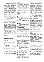
7.2 Fitting the fluid tank (fig. 9)
Push in the tank (A) into the upper or the lower
plug-in device (9) on the guide bar (8),
dependant on the height of the motor. Push
the upper part of the tank firmly against the
guide bar, so that the snap connection (B) snaps
in. Secure against loosening with the swivel
bracket (E).
Suspending the Bowden cable
Fit the lug end of the Bowden cable in the
hook (6) of the dosing lever (5). Clamp
the free hanging bowden cable with the
sleeve (C) intothe holding slot (7) at the
side of the switch housing (4). Adjust the
Bowden cable with the adjusting screw
(D) in such a way, that the valve opens
when the dosing lever (5) is pulled, and
that it closes again completely after
releasing the lever. During working the
chemical is added by pulling the dosing
lever (5).
Push the clear tube (F) firmly into the bore,
or the hose nipple (14) on the machine
body (16). With machine E 250 the plastic
plug on the machine body (16) must be
removed first.
Bring the tank (A) into the optimal filling
position by lowering the guide bar. Fill the tank
with cleaning fluid (by E 250 max. 6 litre; by E
400 S, E 500 S/E and E 430 max. 15 litre).
During working the cleaning fluid is added by
pulling the dosing lever (5).
Do not fill with liquids with a
temperature higher than 40°C!
Only use the cleaning fluid
recommended by the unit
manufacturer.
Under no circumstances must
cleaning fluids be used which
contain easily combustible,
inflammable,poisonous, health
endangering, corrosive or
irritating materials.
Do not exceed the maximum filling
quantity!
7.3 Fitting the vac unit and changing the
paper bag
The vac unit is not suitable for vacu-
uming noxious and /or damp dust!
7.3.1 Fitting the suction ring (fig. 10)
Put the guide bar (8) into a vertical position
(see point 4.3.1) and tilt the machine backwards
(with model E 400 S and E 500 S/E engage the
hinged undercarriage first as described in point
4.3.1), so that the switch housing rests on the
floor.
Put on the suction ring (G) appropriate for the
machine series above the machine body (16).
The hose connecting piece must be aligned to
the floor and the bristles must point away from
the machine. Put the machine upright (with E
400 S and E 500 S/E disengage undercarriage)
and bring the guide bar back to the working
position. When fitted correctly the suction ring
(G) slides across the floor and is seated loosely
around bumper (23) of the machine body (16).
8
23
G
4
16
D
A
E
B
14
9
8
16
D
7
5
C
4
6
F
9

