14
EC3-680-3 February 2017
Order # 5041558-0 & 5041679-0
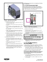
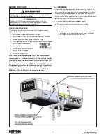
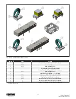
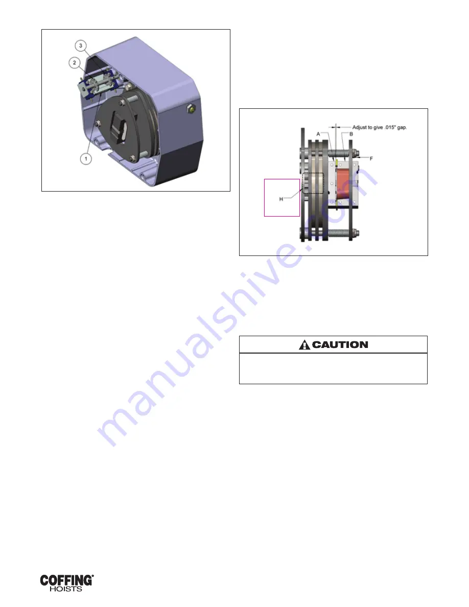
FIGURE 5-1. LIMIT SWITCH ADJUSTMENT
a. Adjusting Upper Limit (Brass Nut).
1. Carefully raise the load block to a point where its top is 3” or
more from the hoist housing.
2. DISCONNECT POWER from the hoist and remove the short
end cover.
3. With a screwdriver. pry the spring guide plate (No. 1 , Figure
5-1) out of the slots in the colored limit switch nuts (Nos. 2
and 3).
4. Tum the slotted brass nut (No. 2) toward its limit switch until
the switch clicks.
5. Release the spring guide plate and be sure it snaps back
into the slots in both nuts. Do not disturb the other slotted
nut if it has been previously set.
6. Replace the short end cover and reconnect power to the hoist.
7. Carefully raise the load block to its upper limit and observe
to see if it stops automatically at the desired point. Do
not allow the load block to run into the hoist housing. The
stopping point should be at least 3” below the hoist housing.
b. Adjusting Lower Limit (Zinc Nut)
1. Carefully lower the load block to a point where at least 12
links of Slack chain hang down from the hoist housing.
2. DISCONNECT POWER from the hoist and remove the short
end cover.
3. Adjust the zinc limit switch nut in the same manner
described above for the red nut.
4. Replace the short end cover and reconnect power to the
hoist.
5. Carefully lower the load block to its lower limit and observe
if it stops automatically at the desired level. Do not run chain
out of hoist or allow the slack end loop to become taut
against the hoist housing. At least 12 links of slack chain
should hang from the hoist.
NOTE: If upper and lower limits are not operating satisfactorily,
repeat adjustment.
5-3. MOTOR BRAKE ADJUSTMENT
When properly adjusted, the multiple disc motor brake should
release promptly, operate without noticeable chatter, and stop the
load with no more than one inch of drift. If the hoist hesitates to lift
the load promptly when the pushbutton is depressed. the brake
should be adjusted per the following procedure.
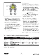
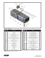
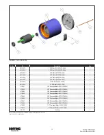
FIGURE 5-2. MOTOR BRAKE ADJUSTMENT
a. Remove any load and DISCONNECT POWER from hoist.
b. Remove the short end cover.
c. Referring to Figure 5-2, check the gap between armature (A)
and frame (B). The correct gap is .015”.
d. Adjust the gap by turning the three lock nuts (F) and check with
a feeler gauge to be sure the gap is the same on both ends of
the solenoid.
Be sure the bottom of the armature does not touch the
splined adapter (H). As wear occurs, the original clearance
will be reduced when this clearance is gone; THE BRAKE
DISCS MUST BE REPLACED.
e. Replace short end cover and reconnect power. If the brake
still chatters or is hesitant to release, refer to Section VI,
Troubleshooting.
5-4. TOP SUSPENSION REMOVAL
AND REPLACEMENT
A number of different top suspension assemblies are available to
accommodate different methods of hanging the hoist. If it should be
necessary to change top suspensions, proceed as follows:
a. DISCONNECT POWER from hoist and move the hoist to a safe
working area. If necessary, remove trolley to gain access to the
cap screws bolting the top suspension to the frame of the hoist.
b. Remove cap screws and lift off the suspension assembly.
NOTE: Due to the variety of mounting arrangements and
different reeving available on EC-3 Series hoists it is possible for
any suspension assembly to be mounted in several positions.
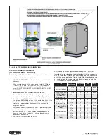
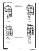
Refer to the diagrams of Figure 5-3 for proper suspension
location and orientation.
c. Check to be sure proper length cap screws are being used with
any change of top suspension. Screws should have ¾ to 1 inch
thread engagement.
d. Install new suspension assembly and tighten cap screws to
75 ft.-lbs. torque.


