


12
EC3-680-3 February 2017
Order # 5041558-0 & 5041679-0
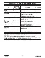
INSPECTOR’S REPORT
ITEM
REMARKS (LlST DEFICIENCIES AND RECOMMENDED ACTION)
Inspector’s Signature
Date Inspected
Approved By
Date
FIGURE 4-2. RECOMMENDED INSPECTOR’S REPORT
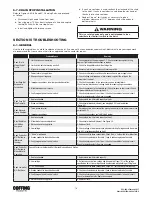
4-3. PERIODIC INSPECTION
The exact period for the following inspections will depend on the
anticipated severity of hoist use. Determination of this period should be
based on the user's experience. It is recommended that the user begin
with a monthly inspection and extend the periods to quarterly, semi-
annually, or annually, based on his monthly inspection experience.
a. Clean hoist of any dirt or foreign material. Inspect bottom block
for accumulation of debris.
b. Perform all frequent inspections listed above.
c. Check for loose bolts, screws and nuts.
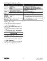
d. Check housings, load block. and other parts for wear,
corrosion, cracks or distortion. Check for abnormal openings
between housing sections.
e. Check motor brake for worn discs, oil contamination or
excessive clearance (see paragraph 5-3).
f. Check mechanical load brake function (see Figure 4-3).
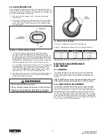
g. Inspect the entire length of chain for gouges, nicks.
weld spatter, corrosion, distortion and wear. See CHAIN
INSPECTION, paragraph 4-5.
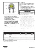
h. Inspect hooks and suspension pans for cracks, distortion or
extreme wear.
i. Inspect hooks for cracks using magnetic particle, dye penetrant
or other crack detecting methods.
j. Check limit switch set points and reset if necessary (see
paragraph 5-2).
k. Inspect all wiring for defective insulation and check to be sure
all electrical connections are tight. Check motor reversing
contactor or relay for burned contacts.
l. Inspect for oil leaks. Check oil level.
m. Inspect for missing or illegible capacity or warning labels.
n. Inspect the supporting structure for continued ability to support
the hoist rated load.
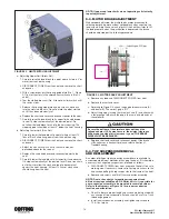
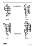
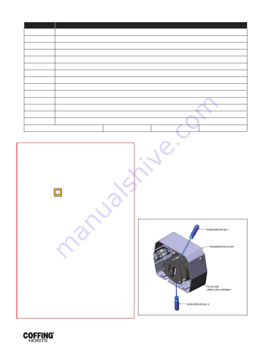
4-4. LOAD BRAKE FUNCTION CHECK
To check the functioning of the mechanical load brake, proceed as
follows:
a. Attach a light load to the hoist and lift it several inches.
b. DISCONNECT HOIST FROM POWER SUPPLY and re move
short end brake cover (see Figure 8-1, Index No. 1).
c. Referring to Figure 4-3 and Figure 8-8, place screwdrivers No. 1
and No. 2 behind the plate and armature assembly and prepare
to pry against the transmission cover.
NOTE: Do not allow either screwdriver to contact brake
disc (see Figure 8-8. Index No. 7).
d. Carefully pry open motor brake (close solenoid gap) and
observe action of load. If the load descends, the mechanical
load brake is malfunctioning and must be repaired.
FIGURE 4-3. LOAD BRAKE FUNCTION CHECK