


USER MANUAL
62
1.
Choose one of the
Rule Number
. It is the number of LCD lines. Maximum 4 lines you
can draw.
2.
Choose the detection target type.
3.
To enable the detection in
Rule Switch
.
4.
Choose a
Rule Type
.
A
B: NVR will only detect the objects move from side A to side B;
B
A: NVR will only detect the objects move from side B to side A;
A
B: NVR will detect the objects move from either side B to side A or side A to side B.
5.
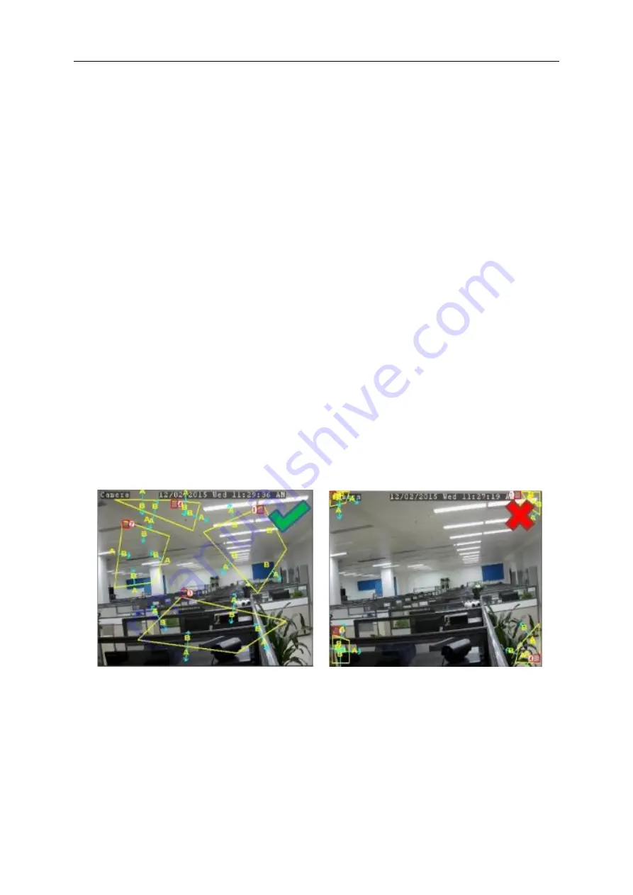
Use your mouse to click 4 points in the camera picture to draw a virtual region. The sharp
of the region should be a convex polygon. Concave polygon will be not able to save.
6.
Click
Save
to save your settings.
7.
If you want to modify the position or sharp of region, click the red box in the region, the
borders of the region will be changed to red color. Click and hold the left button of your
mouse to move the position of the region, or drag the corners to resize the region.
8.
If you want to remove one of the regions from the camera picture, click the red box in the
region and then click
Remove
button. Click
Remove All
will delete all regions.
Notes
:
1)
The perimeter shall not be too close to the edges/corners of the camera picture, since it
may fail to trigger the detection when the target pass through the edges/corners.
2)
The shape of the regions shall not be too narrow/small, since it may fail to trigger the
detection when the target passes through outside the perimeter.


