3-15
Jump Start Studs
This receptacle allows for “jump starting” of the
engines. The receptacles have protective covers.
Be sure covers are installed when receptacles are
not being used. These can be used, when the
batteries are low or removed, to raise the engine
compartment.
Battery Switches
Your Cobalt 360 Performance Cruiser is equipped
with three battery switches located under the aft
port cockpit seat cushion in the rear of the boat.
The battery switch connects one or two batteries
to the electrical circuit of an engine or generator.
The switch provides isolation and positive
disconnect of the battery to protect against
tampering, electrical fire hazards and battery
rundown. Rotate the switch to the OFF position
when the boat is not in use.
The starboard battery switch is connected to the
starboard engine’s charging system. The center
battery switch is connected to the generator’s
charging system and cabin 12 VDC components.
The port battery switch is connected to the port
engine’s charging system. Refer to the battery
switch user’s manual for additional information.
NOTICE: The automatic bilge pump
circuit will remain energized even with
the battery switches in the OFF
position.
Windlass Breaker
This breaker must be on for windlass operation.
Circuit Breakers
These five 40-amp circuit breakers protect the
following circuits:
●
Helm
●
Trim Tabs
●
Amp
●
Cabin Distribution Panel
●
Bilge Pumps
!
WARNING
Do not turn a battery switch to the OFF
position while the engine is running.
Serious electrical system damage could
occur.
Locate and correct the cause of a tripped breaker,
push to reset. If the button continues to pop out,
consult your Cobalt dealer.
Voltage Relay
Allows the starboard engine alternator to charge
the house battery automatically.
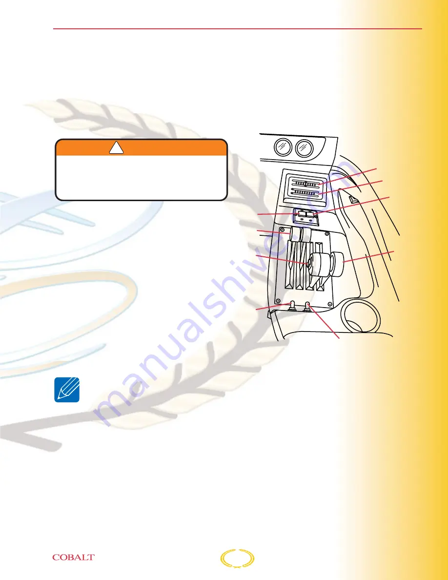
Shift/Throttle Control Panel
1. Drive Unit Trim Indicator
2. Trim Tab Indicator
3. Port Trim Tab Switch
4. Starboard Trim Tab Switch
5. Shift Levers
6. Throttle Levers
7. Combination Port and Starboard Drive Units
Trim Switch
8. Port Drive Unit Trim Switch
9. Starboard Drive Unit Trim Switch
Indicators
The indicators display the relative position of the
drive units and trim tabs. The top indicator set
displays the IN and OUT position of the drive
units. The bottom indicator set displays the UP
and DOWN position of the trim tabs.
COB006
OUT
UP
DN
IN
1
2
3
4
5
6
7
8
1
2
3
4
5
6
7
8
DRIVES
TABS
2
3
7
8
9
5
4
6
1
Operating Information
Summary of Contents for 360
Page 1: ...Owner s Manual ...
Page 36: ...2 22 ...
Page 74: ...3 38 ...
Page 108: ...5 14 ...
Page 111: ...6 3 SERVICE LOG Date Hour Reading Service Repairs Performed Checklist Forms and Index ...
Page 112: ...6 4 FUEL LOG Date Gallons Hours Gallons Hour Date Gallons Hours Gallons Hour ...
Page 118: ...6 10 ...
Page 119: ......


