Operating Instructions
Zero-4 / 5-Channel Stepper Controller
CNC-STEP GmbH & Co. KG ▪ Siemensstrasse 13-15 ▪ 47608 Geldern ▪ Germany
Page 16
Support: +49 (0)2831/91021-50
6/16/2021
4 .3 . 2
Control signals (ST)
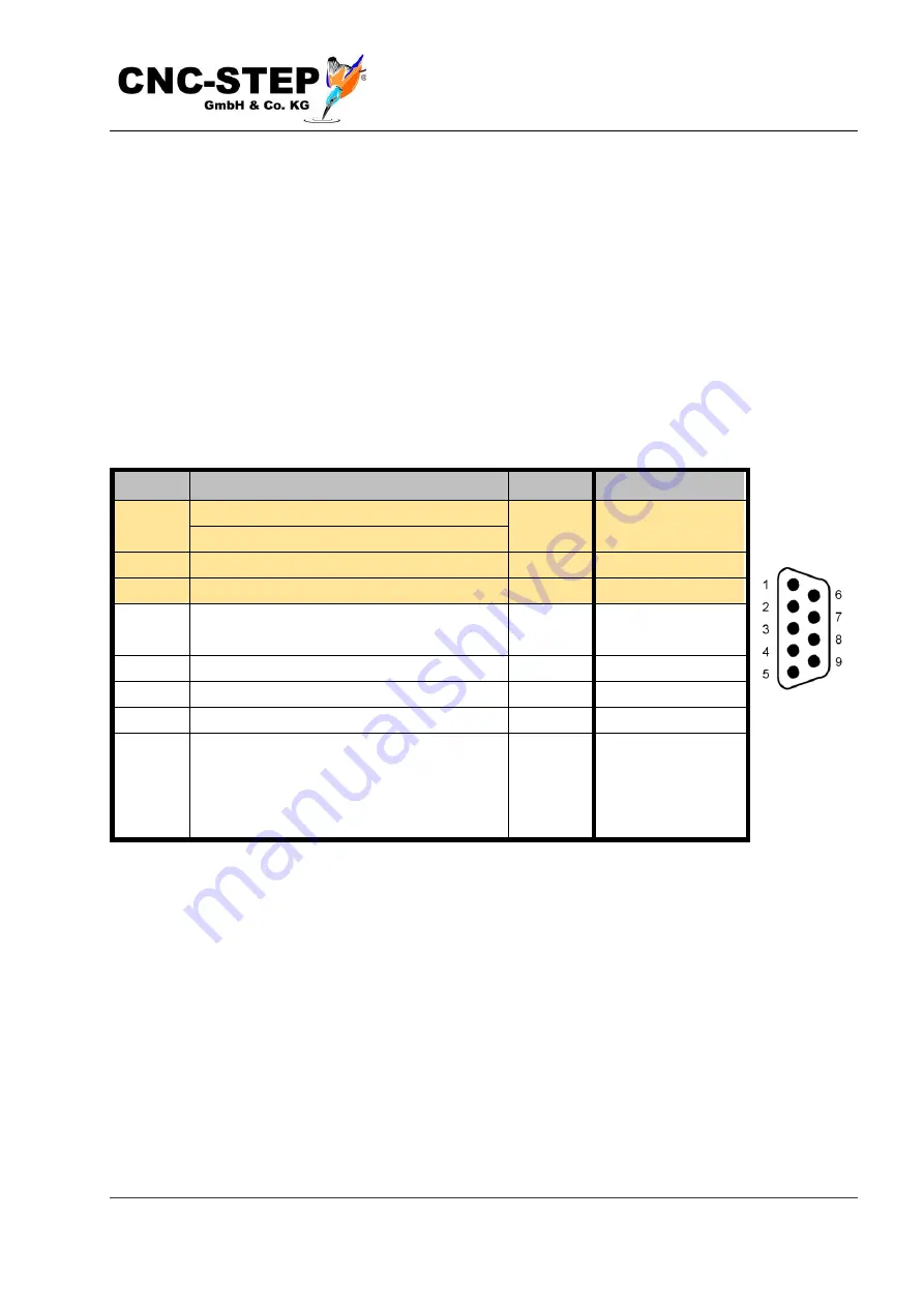
On this plug, limit switch and emergency stop are connected.
Emergency stop must be an opener.
In contrast to the Zero-3, the switch inputs are now designed for PNP sensor types.
When using mechanical or magnetic (reed) switches, the switch must be connected b24V
(pin 9) and pin 1 to 5. This is compatible with the Zero-3, where pin 9 was signal mass !
For inductive sensors, the following applies: blue wire at pin 6 (-), black ones at pin 1 to 4, brown
ones (+) at pin 9.
Pin No. signal
Color* Software PIN
1
Limit switch C or length switch
grey
LPT1 - PIN15 (-)
2
Limit switch X
pink
LPT1 - PIN13 (-)
3
Limit switch Y
green LPT1 - PIN12 (-)
4
Limit switch Z
brown LPT1 - PIN10 (-)
5
Emergency stop (closed = OK, open =
stop)
white LPT1 - PIN11 (-)
6
Signal mass
7
optional holding brake (+24V)
8
optional holding brake (mass)
9
+24V sensor supply
frame Shielding, if available.
Attention: do not connect to PIN9!
( was mass, is now +24V!
yellow
* Color of the wires of the 6-wire ST connection cable
The holding brake, if available, please only connect to pin 7 and 8. The mass of pin 8 may not be
used as a signal mass or for other purposes, since it runs together with pin 7 via a suppression
choke.
In the case of asymmetric currents, this leads to EMC problems. Pin7's 24V are generated by PWM
from the 48V power supply and may only be used for a holding brake or other passive consumers,
not for sensors or sensitive electronics.


