MAN.234 Rev.3 ENG - Use and maintenance manual S19HD (PRO)
page
28
of
83
SIMULTANEOUSLY. Once the feet will all have touched the
ground, it will be possible to continue running short alternate
cycles before on the two front stabilizers and then on the two
rear ones.
Verify that the maximum slope to stabilize not exceed 26°
(49%).
The lowering of the outriggers leads first to the contact of the four stabi-
lizers feet with the ground and then to the lifting of the frame.
Check the levelling of the machine at the bubble level (Picture 16): the
maximum inclination of the frame allowed is equal to 1° (one degree).
When the stabilization ends, you can see the switching on of the consent
light for the aerial part
7
(Picture 4) on the ignition case.
4.4.2.1
Automatic stabilization with radio control
If you want to stabilize the machine in automatic mode, you can use the
radio control:
•
use the lever
11
(Picture 8):
it causes the simultaneous descent
of the four outriggers until the system reads the four limit switch-
es for the ground contact and the lifting of the tracks;
•
make sure that the consent indicator for the use of the aerial part
7
(Picture 4) is on.
During stabilization phase, pressing the parking button
P
(Picture 8), to-
gether the stabilization lever, you can raise all the machine without waiting
the predefined cycle of automatic stabilization.
4.4.3
Access to the basket
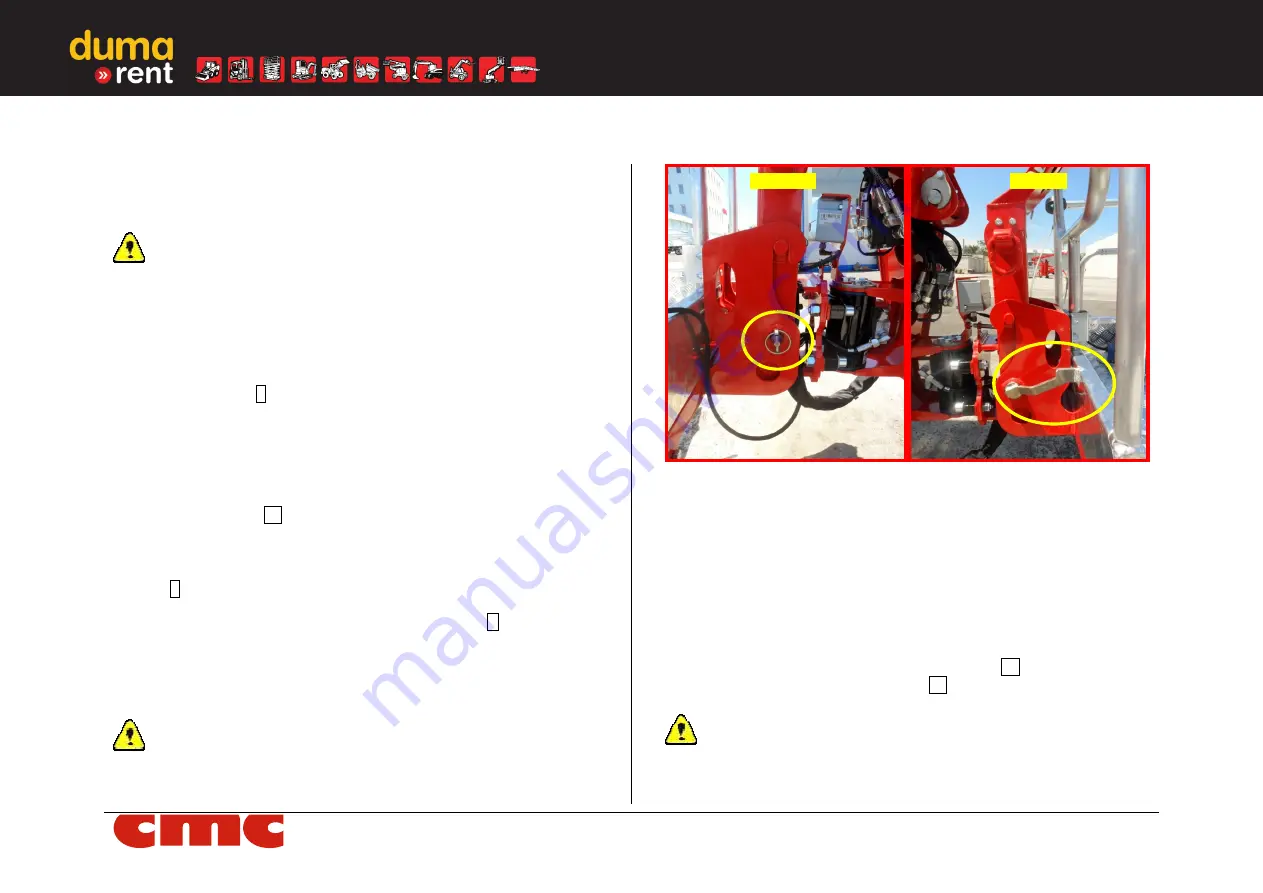
Verify the correct assembly (Picture 19) of the basket to the jib: piv-
ot and cotter pin inserted on the right side of the jib; pin turned to the
right, up to basket edge on the left side.
Picture 19: basket assembly.
11. Use the steps of the ladder and access inside the basket by lifting
the self-locking bar.
12.
Make sure that the bar is back to the closed position; fasten the
safety belts to suitable eyelets present in the basket.
4.4.4
Levelling the basket
13. Perform the basket levelling manoeuvre to return the basket in the
horizontal position if it is out of level. Using the radio control station,
actuate the basket levelling control joystick
J1
and simultaneously
bring down the "dead man" lever
12
in the lower right side (Picture
8).
Perform levelling only with the MEWP aerial part in transport
configuration
(jib closed, pantograph and booms returned, turret
centered).
Left side
Right side
www.
duma
-rent.com


