11
DSP Mute Control
As detailed on the previous page, each unit is provided with an optically isolated
open-collector output for the mute signal which is accessed through the DSP socket
on the master. Muting of the microphones has to be performed by a DSP. If using IR
remote then it will not be possible to mute.
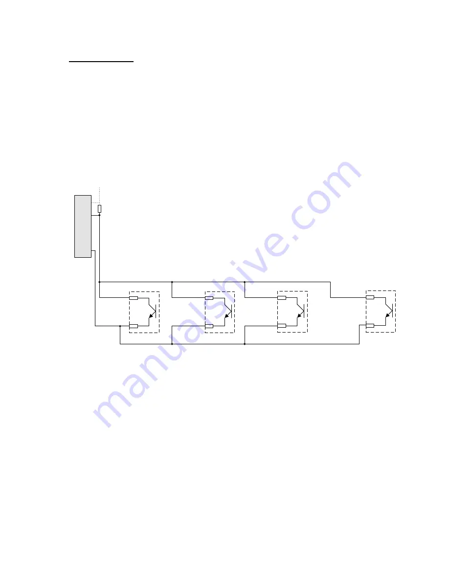
The drawing below represents an equivalent circuit for the mute signal which shows
how the open collector output on each Retacta is connected in parallel when the
units are connected together using the correct RJ45 connection cable.
Mute Signal Equivalent Circuit
SK3 Pin 3
SK3 Pin 4
SK3 Pin 3 or
SK4 Pin 3
Master
SK3 Pin 4 or
SK4 Pin 4
Slave 1
SK3 Pin 3 or
SK4 Pin 3
SK3 Pin 4 or
SK4 Pin 4
Slave 2
SK3 Pin 3 or
SK4 Pin 3
SK3 Pin 4 or
SK4 Pin 4
Slave ‘n’
DSP
Unit
Pull-Up Resistor
(10K Ohm)
V
DSP
I/P
Common Mute Signal
Common Mute Signal Return
To function correctly, the common mute signal from all units must be connected via
an external resistor (not supplied) pull-up resistor to an arbitrary voltage (V) at the
DSP as illustrated above. The arbitrary pull-up voltage (e.g. 5V DC or 12V DC) can
either be supplied by the DSP itself (preferred option), or by an external voltage
source, although if an external voltage source is used, the 0V return must be
common with the DSP 0V.
When the microphones are not deployed, the voltage on the common mute signal
will be pulled to the common signal return (logic low at the DSP input). The DSP
input will only switch to the logic high state when all microphones are deployed and
resting at the preset height.
Note that the common mute signal must be provided with an external voltage through
a 10K Ohm pull-up resistor, the mute signal will not function without this.


