


3
1.4. System Deployment
The Control Panel is designed to be wall
mounted, follow guidelines below when
planning installation location:
The Control Panel requires Ethernet
connection and/or SIM Card..
The Control Panel should be installed at a
location that is hidden from outside view.
You can use the Control Panel
’s built-in
Keypad for entry control. In this case,
install the Control Panel close to your main
entrance.
The Control Panel should be protected by
sensors so that no intruder can reach the
Control Panel without first activating
sensor.
When using ZigBee routers to improve
ZigBee network coverage, remember to
use only ZigBee Router with backup
batteries for security sensors. If you use a
Router without backup battery for security
sensors, the Router will be powered down
in case of AC failure, and you security
sensors will lose connection with the
ZigBee network.
Home
Automation
devices
(Power
Switches
…etc) do not have this limit and
can be used with any Router.
1.5. How to Install the Control
Panel
The easiest way to get to know the system
and get it up and running quickly is to get
all
the
devices
and
accessories
programmed on a tabletop before locating
and mounting them.
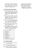
Step 1.
Remove the Control Panel SIM card
and battery compartment cover on
the back. (
Figure 1
)
Step 2.
For VST-2752, insert the SIM Card in
to the SIM card base. (
Figure 2
)
Step 3.
Connect Ethernet cable and power
adaptor to the Control Panel, slide
battery switch to ON position.
(
Figure 3
) Replace the SIM card
compartment cover.
Step 4.
Find the mounting plate included in
the package. Use the holes on the
plate to mark location on the wall at
chest height. (
Figure 4
)
Step 5.
Drill 2 holes into the mark location
and insert wall plug if required.
(
Figure 5
) Screw the mounting plate
onto the wall at marked location.
(
Figure 6
)
Step 6.
Hook the Control Panel onto the
plate, then slide the control panel left
to secure the panel and depress the
tamper switch against the mounting
plate. (
Figure 7
)
Figure 1
Figure 2
Figure 3