


2
1.2. Introduction
VST-2735/2745/2752 series Control Panels
feature IP and/or GSM/GPRS reporting
functions:
VST-2735 – IP Reporting
VST-2745 – GSM/GPRS Reporting
VST-2752 – IP + GSM/GPRS Reporting
The advanced IP Security System with fully
integrated TCP/IP technology and Ethernet
connectivity is able to take full advantage of
new advances in IP Home Security and Home
Automation and multi-path signalling.
Remote control of the panel is achieved by
registering the panel in our
Home Portal
Server
. With
Home Portal Server
, you can
connect to your panel anytime, anywhere in the
world through internet connection either with a
computer or a smartphone using our Vesta
Home application. Please refer to our Home
Portal User Guide for detail about registering
and using
Home Portal Server
.
For VST-2745 and VST-2752, SMS remote
programming and command is also available to
configure your panel by SMS messages. You
can also use our Vesta EZ Home smartphone
applications to send the SMS commands easily
for basic panel functions.
GSM/GPRS SIM card:
VST-2745 and VST-2752 Panel feature built-in
GSM/GPRS
communication facility to report to
the Monitoring Station. To use the GSM/GPRS
function, a SIM card is required.
<NOTE>
Please disable the SIM card PIN code
before inserting into the Control Panel.
Please make sure the SIM card GPRS
and MMS functions are activated
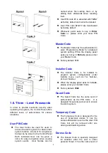
Unlock the SIM card base by sliding the
cover toward
OPEN
direction.
Spring open the SIM card slot and insert
your new SIM card.
Replace the SIM slot onto the base lightly.
Remember to lock the SIM card base by
sliding the cover toward
LOCK
direction.
1.3. The Power Supply
An AC power adaptor is required to connect to
a wall outlet. Be sure only to use an adaptor
with the appropriate AC voltage rating to
prevent component damage.
A DC 9V output and 1A switching power is
generally used to power the Control Panel.
Rechargeable Battery
In addition to the adapter, there is a
rechargeable
battery
inside
the
Control Panel that serves as a backup
powering source in case of any power
failure condition.
During normal operation, the AC
power adapter is used to supply
power to the Control Panel and at the
same time recharge the battery. It
takes approximately 72 hours to fully
charge the battery.
Battery Switch is set as
OFF
by
factory default, the battery will not be
charged when AC power is connected,
nor will it serve as a back-up power
source when AC power is missing.
You need to switch the battery to
ON
after supplying AC power to Control
Panel.